Масляный Насос -- Установка |
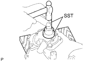
| 1. INSTALL OIL PUMP SEAL |
Using SST and a hammer, tap in a new oil seal until its surface is flush with the oil pump edge.
- SST
- 09223-22010
- ПРИМЕЧАНИЕ:
- Tap in the oil seal vertically.
 |
Apply MP grease to a new oil seal lip.
- ПРИМЕЧАНИЕ:
- Keep the lip free of foreign objects.
| 2. INSTALL OIL PUMP ASSEMBLY |
Install 2 new O-rings onto the 2 portions as shown in the illustration.
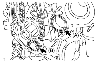 |
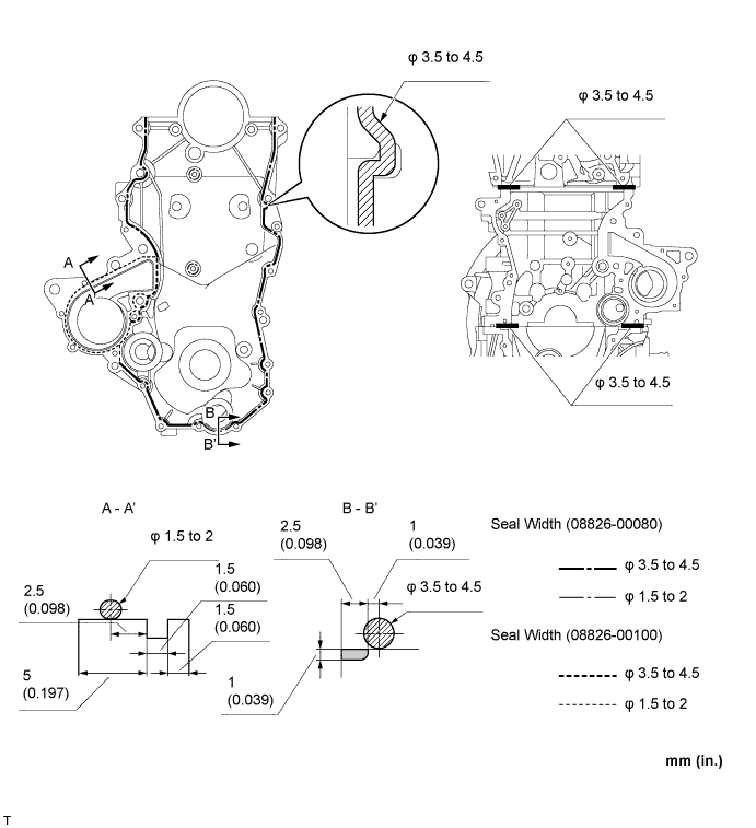
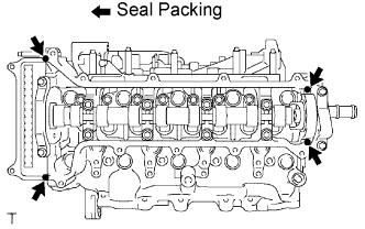
Apply seal packing to the engine body and oil pump as shown in the illustration below.
- Seal packing:
Position Item (A) Toyota Genuine Seal Packing 1282B, Three Bond 1282B or equivalent (B) Toyota Genuine Seal Packing Black, Three Bond 1207B or equivalent
- ПРИМЕЧАНИЕ:
- Remove any oil from the contact surface.
- Install the oil pan within 3 minutes, and tighten the bolts within 15 minutes of applying seal packing.
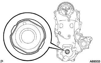
Align the keyway of the oil pump drive rotor with the rectangular portion of the crankshaft, then slide the oil pump into place.
 |
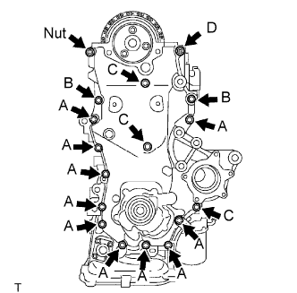
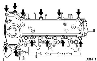
Install the oil pump assembly with the 16 bolts and nut as shown in the illustration.
- Момент затяжки:
- Bolt A:
- 11 Н*м{112 кгс*см, 8 фунт-сила-футов}
- Bolt B:
- 24 Н*м{245 кгс*см, 18 фунт-сила-футов}
- Bolt C:
- 11 Н*м{112 кгс*см, 8 фунт-сила-футов}
- Bolt D:
- 24 Н*м{245 кгс*см, 18 фунт-сила-футов}
- Nut:
- 24 Н*м{245 кгс*см, 18 фунт-сила-футов}
- ПРИМЕЧАНИЕ:
- Be careful not to let the chain come into contact with the seal packing when installing the oil pump.
- Install the engine mounting bracket RH and water pump within 15 minutes of installing the oil pump.
- УКАЗАНИЕ:
- The bolt lengths are as follows.
- Bolt A: 20 mm (0.79 in.)
- Bolt B: 30 mm (1.18 in.)
- Bolt C: 35 mm (1.38 in.)
- Bolt D (double ended bolt): 20 and 14 mm (0.79 and 0.55 in.)
 |
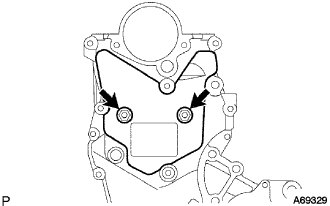
| 3. INSTALL NO. 2 TIMING CHAIN COVER |
Install the No. 2 timing cover with the 2 bolts.
- Момент затяжки:
- 5.5 Н*м{56 кгс*см, 49 фунт-сила-дюймов}
 |
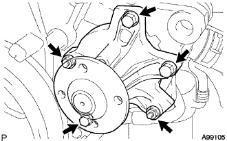
| 4. INSTALL WATER PUMP ASSEMBLY |
Install a new gasket and the water pump with the 3 bolts and 2 nuts.
- Момент затяжки:
- 11 Н*м{112 кгс*см, 8 фунт-сила-футов}
 |
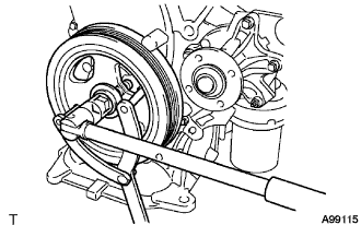
| 5. INSTALL WATER PUMP PULLEY |
Temporarily install the water pump pulley with the 4 bolts.
 |
Using SST, hold the water pump pulley.
- SST
- 09960-10010(09962-01000,09963-00700)
Tighten the 4 bolts to the specified torque.
- Момент затяжки:
- 15 Н*м{153 кгс*см, 11 фунт-сила-футов}
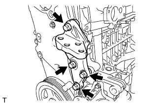
| 6. INSTALL TRANSVERSE ENGINE ENGINE MOUNTING BRACKET |
Install the engine mounting bracket with the 4 bolts.
- Момент затяжки:
- 55 Н*м{561 кгс*см, 41 фунт-сила-футов}
 |
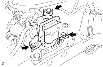
| 7. INSTALL ENGINE MOUNTING INSULATOR SUB-ASSEMBLY RH |
Install the engine mounting insulator RH with the 3 bolts.
- Момент затяжки:
- 95 Н*м{969 кгс*см, 70 фунт-сила-футов}
 |
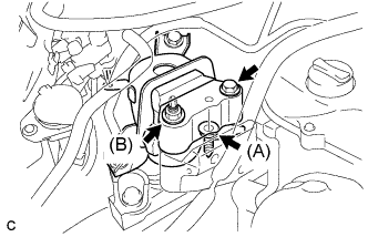
Install the engine mounting insulator RH to the engine mounting bracket with the bolt and 2 nuts.
- Момент затяжки:
- Bolt:
- 95 Н*м{969 кгс*см, 70 фунт-сила-футов}
- Nut(A):
- 95 Н*м{969 кгс*см, 70 фунт-сила-футов}
- Nut(B):
- 52 Н*м{530 кгс*см, 38 фунт-сила-футов}
 |
Install the air conditioner pipe bracket with the bolt and nut.
- Момент затяжки:
- 9.8 Н*м{100 кгс*см, 87 фунт-сила-дюймов}
 |
| 8. INSTALL CRANKSHAFT DAMPER SUB-ASSEMBLY |
Align the key with the key groove of the crankshaft damper, and slide the crankshaft damper to the crankshaft.
Using SST, fix the crankshaft damper.
- SST
- 09960-10010(09962-01000,09963-01000)
 |
Tighten the bolt to the specified torque.
- Момент затяжки:
- 180 Н*м{1,835 кгс*см, 133 фунт-сила-футов}
| 9. INSTALL VACUUM PUMP ASSEMBLY |
Нанесите моторное масло на 2 новых кольцевых уплотнения и установите их в вакуумный насос в сборе.
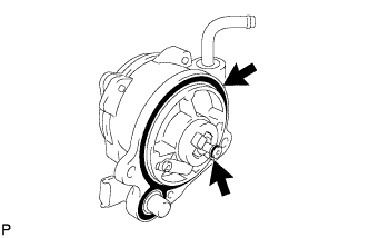 |
Нанесите моторное масло на маслопровод на кончике вакуумного насоса в сборе.
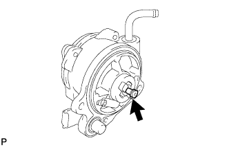 |
Установите вакуумный насос в сборе так, чтобы соединительный зубец (A) со стороны вакуумного насоса вошел в зацепление с канавкой (B) распредвала.
 |
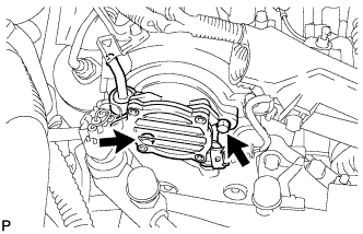
Закрепите вакуумный насос в сборе 2 новыми болтами.
- Момент затяжки:
- 21 Н*м{214 кгс*см, 15 фунт-сила-футов}
 |
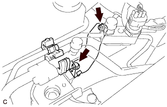
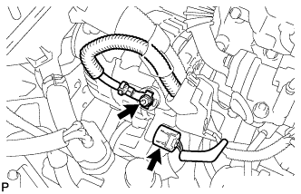
Подсоедините вакуумный шланг к вакуумному насосу в сборе и сдвиньте фиксатор.
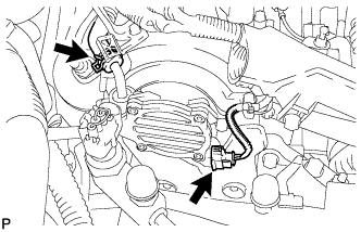 |
Подсоедините разъем датчика положения распредвала.
| 10. INSTALL CYLINDER HEAD COVER SUB-ASSEMBLY |
Install the cylinder head gasket onto the cylinder head cover.
 |
Apply seal packing to the 4 locations shown in the illustration, then install the cylinder head cover.
- Seal packing:
- Toyota Genuine Seal Packing Black, Three Bond 1207B or equivalent
- ПРИМЕЧАНИЕ:
- Remove any oil from the contact surface.
- Install the cylinder head cover within 3 minutes, and tighten the bolts within 15 minutes of applying the seal packing.
Temporarily tighten the cylinder head cover with the 12 bolts.
 |
Tighten the bolts to the specified torque as shown in the illustration.
- Момент затяжки:
- 13 Н*м{133 кгс*см, 10 фунт-сила-футов}
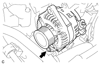
| 11. INSTALL GENERATOR ASSEMBLY |
Temporarily install the generator with the bolt.
 |
Temporarily install the fan belt adjusting slider with the bolt and nut, then move the generator toward the cylinder block and tighten the nut.
- Момент затяжки:
- 19 Н*м{189 кгс*см, 14 фунт-сила-футов}
 |
Install the connector.
 |
Install terminal B with the nut.
- Момент затяжки:
- 9.8 Н*м{100 кгс*см, 87 фунт-сила-дюймов}
Install the terminal cap.
| 12. INSTALL V-RIBBED BELT |
Temporarily install the v-ribbed belt onto each pulley.
- ПРИМЕЧАНИЕ:
- Before installing the V belt, check each pulley for any kind of liquid and chips.
- Check that the ribs of the V belt are correctly fitted into the grooves of the pulleys.
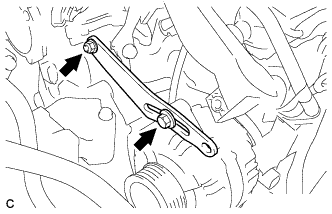
| 13. ADJUST V-RIBBED BELT |
Insert a bar between the generator and the engine. Pull the bar toward the front of the vehicle and adjust the tension.
 |
Tighten bolt A, then tighten bolt B.
- Момент затяжки:
- Bolt A:
- 19 Н*м{189 кгс*см, 14 фунт-сила-футов}
- Bolt B:
- 32 Н*м{326 кгс*см, 24 фунт-сила-футов}
 |
| 14. INSPECT DRIVE BELT DEFLECTION AND TENSION |
Inspect the v-ribbed belt deflection.
- Pressing force:
- 98 N (10 kgf, 221 lbf)
New belt
mm (in.)Used belt
mm (in.)5.0 to 6.0
(0.197 to 0.236)7.0 to 8.5
(0.276 to 0.335)
Inspect the v-ribbed V belt tension.
New belt
N (kg, lb)Used belt
N (kg, lb)980 to 1176
(100 to 120, 220 to 264)490 to 686
(50 to 70, 110 to 154)- ПРИМЕЧАНИЕ:
- Check the V belt deflection at the specified point.
- When installing a new belt, set its tension value as specified.
- When checking a belt used for over 5 minutes, confirm that the deflection value is within the specified range for a used belt.
- When reinstalling a belt used for over 5 minutes, check whether its deflection value is within the specified range for the used belt.
- When using a belt tension gauge, confirm its accuracy first by using a master gauge.
| 15. CONNECT CABLE TO NEGATIVE BATTERY TERMINAL |
- Момент затяжки:
- 5.4 Н*м{55 кгс*см, 48 фунт-сила-дюймов}
| 16. ADD ENGINE COOLANT |
Tighten the radiator drain cock plug.
Add TOYOTA Super Long Life Coolant (SLLC) to the radiator reservoir filler opening.
- Standard capacity:
Item Specified Condition without Power heater 5.4 liters (5.7 US qts, 4.8 lmp. qts) with Power heater 5.8 liters (6.1 US qts, 5.1 lmp. qts)
- УКАЗАНИЕ:
- TOYOTA vehicles are filled with TOYOTA SLLC at the factory. In order to avoid damage to the engine cooling system and other technical problems, only use TOYOTA SLLC or similar high quality ethylene glycol based non-silicate, non-amine, non-nitrite, non-borate coolant with long-life hybrid organic acid technology (coolant with long-life hybrid organic acid technology consists of a combination of low phosphates and organic acids).
- Contact your TOYOTA dealer for further details.
- ПРИМЕЧАНИЕ:
- Never use water as a substitute for engine coolant.
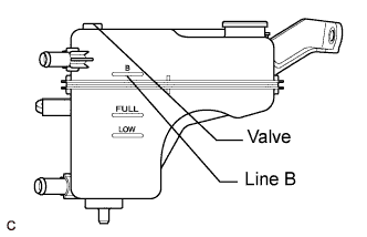
Remove the radiator cap and air-bleeding valve and add coolant to line B of the reservoir tank.
 |
Press the inlet and outlet radiator hoses several times by hand, and then check the level of the coolant.
If the coolant level is low, add coolant.
Install the cap and valve, and warm up the engine sufficiently.
Bleed air from the cooling system.
- ПРИМЕЧАНИЕ:
- Before starting the engine, turn the A/C switch OFF.
- Adjust the air conditioner set temperature to MAX (HOT).
- Adjust the air conditioner set blower to Lo.
Warm up the engine until the thermostat opens. While the thermostat is open, allow the coolant to circulate for several minutes.
- УКАЗАНИЕ:
- The thermostat opening timing can be confirmed by squeezing the inlet radiator hose by hand, and sensing vibrations when the engine coolant starts to flow inside the hose.
- ПРЕДОСТЕРЕЖЕНИЕ:
- When squeezing the radiator hose:
- Wear protective gloves.
- Be careful as the radiator hoses are hot.
- Keep your hands away from the radiator fan.
After the engine has warmed up, run the engine using the following cycle for at least 7 minutes: at 3000 rpm for 5 seconds, at idle speed for 45 seconds. (Repeat this cycle at least 8 times.)
Squeeze the inlet and outlet radiator hoses several times by hand to bleed air from the system.
- ПРЕДОСТЕРЕЖЕНИЕ:
- When squeezing the radiator hose:
- Wear protective gloves.
- Be careful as the radiator hoses are hot.
- Keep your hands away from the radiator fan.
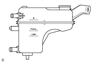
After the engine has cooled down, check that the coolant level is between FULL and LOW.
If the coolant level is low, add coolant to the reservoir tank F line.
 |
| 17. ADD ENGINE OIL |
Fill with fresh engine oil.
- Engine oil:
Oil Grade Oil Viscosity (SAE) - ACEA B1
- API CF-4 or CF (you may also use API CE or CD.)
- 5W-30
- 10W-30
- 15W-40
- 20W-50
- ACEA B1
- Capacity:
Item Fill amount Drain and refill with oil filter change 4.3 liters (4.5 US qts, 3.8 lmp. qts) Drain and refill without oil filter change 3.8 liters (4.0 US qts, 3.3 lmp. qts) Dry fill 4.8 liters (5.1 US qts, 4.2 lmp. qts)
| 18. INSPECT FOR COOLANT LEAK |
- ПРЕДОСТЕРЕЖЕНИЕ:
- To avoid the danger of being burned, do not remove the radiator cap sub-assembly while the engine and radiator assembly are still hot. Thermal expansion will cause hot engine coolant and steam to blow out from the radiator assembly.
Fill the radiator assembly with engine coolant, then attach a radiator cap tester.
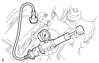 |
Pump it to 108 kPa (1.1 kgf/cm2, 15.6 psi), then check that the pressure does not drop.
If the pressure drops, check the hoses, radiator assembly and water pump assembly for leakage. If there are no signs or traces of external engine coolant leakage, check the heater core, cylinder block and head.
| 19. INSPECT ENGINE OIL LEVEL |
Warm up the engine. Then stop the engine and wait for 5 minutes.
Check that the engine oil level is between the 2 marks on the oil level gauge.
If low, check for leakage and top up oil to the upper mark.- ПРИМЕЧАНИЕ:
- Do not add engine oil to above the upper mark.
| 20. INSPECT FOR OIL LEAK |
| 21. INSTALL ENGINE UNDER COVER |
| 22. INSTALL NO. 1 ENGINE COVER |
Fit the 4 retainers and install the No. 1 engine cover.
| 23. INSTALL FRONT WHEEL RH (for RH Side) |
- Момент затяжки:
- 103 Н*м{1050 кгс*см, 76 фунт-сила-футов}