Выпускной Коллектор Установка. Corolla Auris
Двигатель. COROLLA, AURIS. ZZE150 ZRE151,152 NDE150
INSTALL EXHAUST MANIFOLD
INSTALL NO. 1 EXHAUST MANIFOLD HEAT INSULATOR
INSTALL TURBO OIL INLET PIPE
INSTALL TURBOCHARGER SUB-ASSEMBLY
INSTALL NO. 1 AIR HOSE
INSTALL TURBO OIL INLET PIPE
INSTALL EXHAUST MANIFOLD CONVERTER SUB-ASSEMBLY
INSTALL NO. 1 TURBO INSULATOR
INSTALL COWL TOP PANEL OUTER (for Sedan)
INSTALL COWL TOP PANEL OUTER (for Hatchback)
INSTALL COWL BODY MOUNTING REINFORCEMENT LH (for Hatchback)
INSTALL WINDSHIELD WIPER MOTOR AND LINK
INSTALL FRONT EXHAUST PIPE ASSEMBLY
INSTALL AIR CLEANER CAP SUB-ASSEMBLY
CONNECT CABLE TO NEGATIVE BATTERY TERMINAL
ADD ENGINE OIL
INSPECT FOR OIL LEAK
INSPECT FOR EXHAUST GAS LEAK
INSTALL NO. 1 ENGINE COVER
Выпускной Коллектор -- Установка |
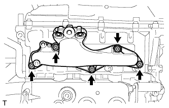
| 1. INSTALL EXHAUST MANIFOLD |
Install a new exhaust manifold gasket.
Install the 5 nuts and 5 spacers, then install the exhaust manifold.
- Момент затяжки:
- 43 Н*м{439 кгс*см, 32 фунт-сила-футов}
Install the 2 bolts and manifold stay.
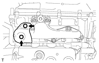
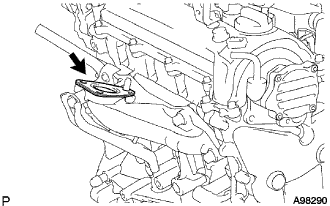
| 2. INSTALL NO. 1 EXHAUST MANIFOLD HEAT INSULATOR |
Install the 2 bolts and No. 1 exhaust manifold heat insulator.
- Момент затяжки:
- 6.0 Н*м{61 кгс*см, 53 фунт-сила-дюймов}
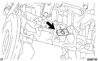
| 3. INSTALL TURBO OIL INLET PIPE |
Install a new gasket onto the cylinder block.
Provisionally install the turbo oil outlet pipe with 2 new nuts.
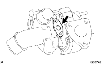
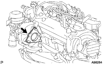
| 4. INSTALL TURBOCHARGER SUB-ASSEMBLY |
Install a new gasket onto the turbocharger.
Install a new gasket onto the exhaust manifold.
Install the turbocharger with the 3 nuts.
- Момент затяжки:
- 53 Н*м{540 кгс*см, 39 фунт-сила-футов}
Connect the vacuum hose to the turbocharger.
Tighten 2 new nuts B.
- Момент затяжки:
- 11 Н*м{110 кгс*см, 8 фунт-сила-футов}
Tighten 2 new nuts A.
- Момент затяжки:
- 14 Н*м{140 кгс*см, 10 фунт-сила-футов}
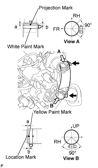
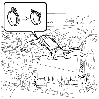
| 5. INSTALL NO. 1 AIR HOSE |
Install the intercooler air hose with the 2 hose clamps.
- Момент затяжки:
- 6.0 Н*м{60 кгс*см, 53 фунт-сила-дюймов}
- Specification:
Area
| Measurement
|
a
| 0 to 2 mm (0 to 0.079 in.)
|
b
| 2 to 5 mm (0.079 to 0.197 in.)
|
- ПРИМЕЧАНИЕ:
- Align the paint mark of the intercooler air hose with the location mark of the turbocharger.
- Align the paint mark of the intercooler air hose with the location mark of No. 1 air tube.
- Make sure that the hose clamp is at the correct angle when installing.
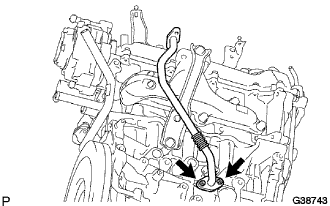
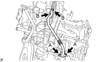
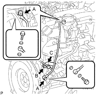
| 6. INSTALL TURBO OIL INLET PIPE |
Install 4 new gaskets and the turbo oil inlet pipe with 2 union bolts A.
- Момент затяжки:
- 24 Н*м{245 кгс*см, 18 фунт-сила-футов}
Tighten bolt B.
- Момент затяжки:
- 11 Н*м{110 кгс*см, 8 фунт-сила-футов}
Install wire harness clamp C.
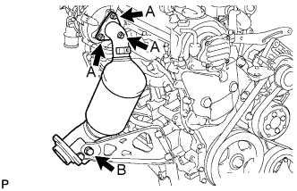
| 7. INSTALL EXHAUST MANIFOLD CONVERTER SUB-ASSEMBLY |
Install a new gasket onto the turbocharger.
Temporarily install the exhaust manifold converter with 3 new nuts A.
Provisionally install the manifold support bracket with the bolt B.
Tighten 3 nuts A.
- Момент затяжки:
- 26 Н*м{265 кгс*см, 19 фунт-сила-футов}
Tighten bolt B.
- Момент затяжки:
- 37 Н*м{375 кгс*см, 27 фунт-сила-футов}
| 8. INSTALL NO. 1 TURBO INSULATOR |
Install No. 1 turbo insulator with the 3 bolts.
- Момент затяжки:
- 6.0 Н*м{60 кгс*см, 53 фунт-сила-дюймов}
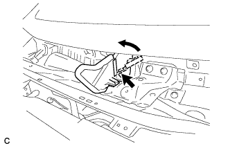
| 9. INSTALL COWL TOP PANEL OUTER (for Sedan) |
Установите наружную верхнюю панель кожуха и закрепите ее 10 болтами.
- Момент затяжки:
- 8,8 Н*м{90 кгс*см, 78 фунт-сила-дюймов}
Отогните правую водозащитную пластину, как показано на рисунке, и введите в зацепление зажим.
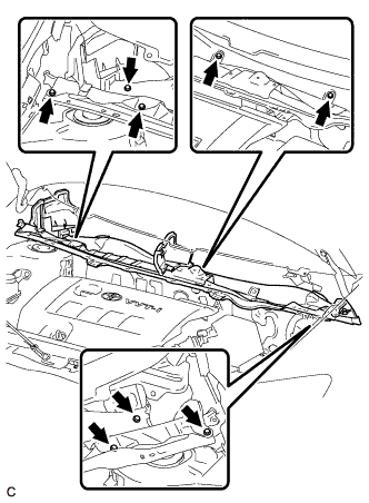
| 10. INSTALL COWL TOP PANEL OUTER (for Hatchback) |
Установите наружную верхнюю панель кожуха и закрепите ее 8 болтами.
- Момент затяжки:
- 8,8 Н*м{90 кгс*см, 78 фунт-сила-дюймов}
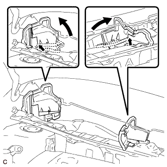
Отогните правую водозащитную пластину и брызгозащитное уплотнение воздуховода отопителя № 1 и отсоедините все зажимы, как показано на рисунке.
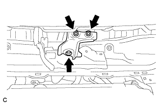
| 11. INSTALL COWL BODY MOUNTING REINFORCEMENT LH (for Hatchback) |
Установите левый усилитель крепления кожуха к кузову и закрепите его 3 болтами.
- Момент затяжки:
- 8,8 Н*м{90 кгс*см, 78 фунт-сила-дюймов}
| 12. INSTALL WINDSHIELD WIPER MOTOR AND LINK |
(See page Нажмите здесь).
| 13. INSTALL FRONT EXHAUST PIPE ASSEMBLY |
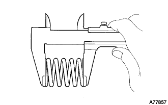
Using vernier calipers, measure the free length of the compression springs.
Minimum (front)
| 41.5 mm (1.63 in.)
|
Minimum (rear)
| 38.5 mm (1.52 in.)
|
- УКАЗАНИЕ:
- If the length is less than minimum, replace the compression spring.
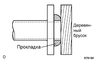
Using a plastic hammer and wooden block, tap in a new exhaust pipe gasket until its surface is flush with the exhaust manifold converter sub-assembly.
- ПРИМЕЧАНИЕ:
- Be careful with the installation direction of the gasket.
- Do not reuse the gasket.
- Do not damage the gasket.
- Do not push in the gasket by using the exhaust pipe when connecting it.
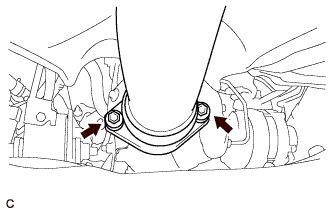
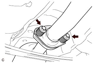
Install the exhaust pipe supports, then install the front exhaust pipe assembly with the 2 compression springs and 2 bolts.
- Момент затяжки:
- 43 Н*м{439 кгс*см, 32 фунт-сила-футов}
Using a plastic hammer and wooden block, tap in a new exhaust pipe gasket until its surface is flush with the front exhaust pipe assembly.
- ПРИМЕЧАНИЕ:
- Be careful with the installation direction of the gasket.
- Do not reuse the gasket.
- Do not damage the gasket.
- Do not push in the gasket by using the exhaust pipe when connecting it.
Install the 2 compression springs and 2 bolts, then connect the front exhaust pipe assembly to the center exhaust pipe assembly.
- Момент затяжки:
- 43 Н*м{439 кгс*см, 32 фунт-сила-футов}
| 14. INSTALL AIR CLEANER CAP SUB-ASSEMBLY |
Install the air cleaner cap sub-assembly, and connect the 2 clamps and band.
Connect the No. 2 ventilation hose.
Connect the mass air flow meter connector.
| 15. CONNECT CABLE TO NEGATIVE BATTERY TERMINAL |
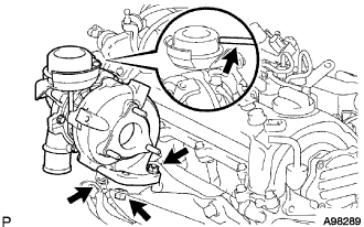
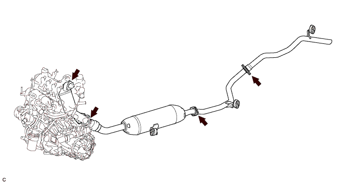
| 18. INSPECT FOR EXHAUST GAS LEAK |
Check that there are no exhaust gas leaks from the points (jointed parts of the exhaust pipes and installed parts of each sensor) shown in the illustration.
| 19. INSTALL NO. 1 ENGINE COVER |
Fit the 4 retainers and install the No. 1 engine cover.