INSTALL FUEL TANK MAIN TUBE SUB-ASSEMBLY (for TMUK, TMMT Made)
INSTALL FUEL TANK RETURN TUBE SUB-ASSEMBLY (for TMUK, TMMT Made)
INSTALL NO. 1 REAR SEAT CUSHION HINGE COVER (for Hatchback RH Side)
INSTALL NO. 2 REAR SEAT CUSHION HINGE COVER (for Hatchback RH Side)
INSTALL NO. 1 REAR SEAT CUSHION HINGE COVER (for Hatchback LH Side)
INSTALL NO. 2 REAR SEAT CUSHION HINGE COVER (for Hatchback LH Side)
Топливный Бак -- Установка |
| 1. INSTALL FUEL TANK MAIN TUBE SUB-ASSEMBLY (for TMC Made) |
Fit the fuel tank main tube into the fuel tank sub-assembly.
 |
| 2. INSTALL FUEL TANK MAIN TUBE SUB-ASSEMBLY (for TMUK, TMMT Made) |
Fit the fuel tank main tube into the fuel tank sub-assembly.
 |
| 3. INSTALL FUEL TANK RETURN TUBE SUB-ASSEMBLY (for TMC Made) |
Fit the fuel tank return tube into the fuel tank sub-assembly.
 |
| 4. INSTALL FUEL TANK RETURN TUBE SUB-ASSEMBLY (for TMUK, TMMT Made) |
Fit the fuel tank return tube into the fuel tank sub-assembly.
 |
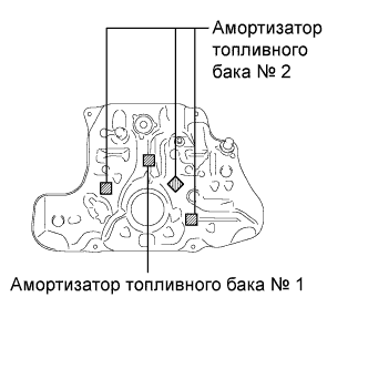
| 5. INSTALL NO. 1 FUEL TANK CUSHION |
Install a new No. 1 fuel tank cushion and 3 new No. 2 cushions as shown in the illustration.
 |
| 6. INSTALL FUEL TANK ASSEMBLY (for TMC Made) |
Support the fuel tank using an engine lifter.
Raise the engine lifter, then install the fuel tank to the vehicle.
- ПРИМЕЧАНИЕ:
- Do not drop the fuel tank.
- When removing the fuel tank, tilt it slightly to prevent it from interfering with the suspension arm or other surrounding parts.
 |
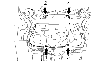
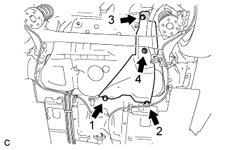
Temporary install the fuel tank with 4 new bolts.
Temporarily tighten bolt 1 and then fully tighten the bolts in the following order: bolt 2, bolt 1, bolt 3, and bolt 4.
- Момент затяжки:
- 39 Н*м{400 кгс*см, 29 фунт-сила-футов}
 |
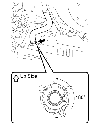
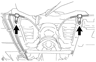
Connect the fuel tank to filler pipe hose to the fuel tank as shown in the illustration, then fit it with the clamp.
- ПРИМЕЧАНИЕ:
- Be careful of the installation angle of the hose clamp.
 |
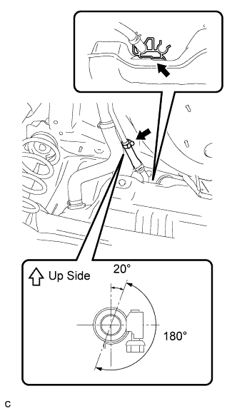
Connect the breather tube fuel hose to the fuel tank inlet pipe as shown in the illustration.
- ПРИМЕЧАНИЕ:
- After connecting the breather tube, check that the evaporation vent tube clamp is securely connected to the fuel tank.
 |
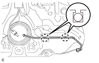
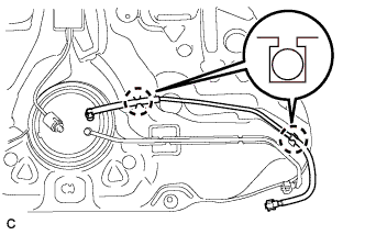
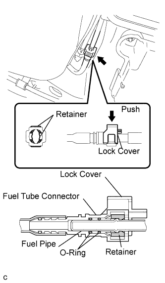
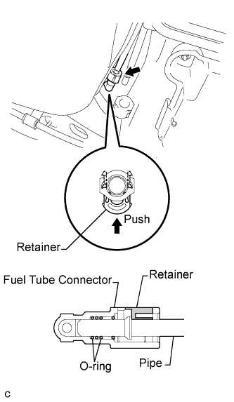
Connect the fuel tank main tube.
Align the fuel tube connector with the pipe, push the fuel tube connector in until the retainer makes a "click" sound, then lock the cover of the connector.
- ПРИМЕЧАНИЕ:
- Check that there are no scratches or foreign objects around the connected part of the fuel tube connector and pipe before starting this step.
- After connecting the fuel tank main tube, check that the fuel tank main tube is securely connected by pulling on the fuel tube connector.

Connect the fuel tank return tube.
Align the fuel tube connector with the pipe, push the fuel tube connector in until the retainer makes a "click" sound, then lock the cover of the connector.
- ПРИМЕЧАНИЕ:
- Check that there are no scratches or foreign objects around the connected part of the fuel tube connector and pipe before starting this step.
- After connecting the fuel tank return tube, check that the fuel tank return tube is securely connected by pulling on the fuel tube connector.
Connect the parking brake cable assembly with the 2 bolts.
- Момент затяжки:
- 6.0 Н*м{61 кгс*см, 53 фунт-сила-дюймов}
 |
| 7. INSTALL FUEL TANK ASSEMBLY (for TMUK, TMMT Made) |
Support the fuel tank using an engine lifter.
Raise the engine lifter, then install the fuel tank to the vehicle.
- ПРИМЕЧАНИЕ:
- Do not drop the fuel tank.
- When removing the fuel tank, tilt it slightly to prevent it from interfering with the suspension arm or other surrounding parts.
|
Temporary install the fuel tank with 4 new bolts.
Temporarily tighten bolt 1 and then fully tighten the bolts in the following order: bolt 2, bolt 1, bolt 3, and bolt 4.
- Момент затяжки:
- 39 Н*м{400 кгс*см, 29 фунт-сила-футов}
|
Connect the fuel tank to filler pipe hose to the fuel tank as shown in the illustration, then fit it with the clamp.
- ПРИМЕЧАНИЕ:
- Be careful of the installation angle of the hose clamp.
|
Connect the breather tube fuel hose to the fuel tank inlet pipe as shown in the illustration.
- ПРИМЕЧАНИЕ:
- After connecting the breather tube, check that the evaporation vent tube clamp is securely connected to the fuel tank.
|
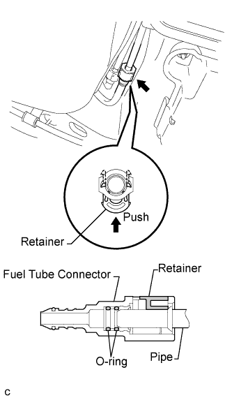
Connect the fuel tank main tube.
Align the fuel tube connector with the pipe, then push the fuel tube connector in until it comes into contact with the seat to connector the fuel tank main tube to the pipe, then push the retainer up until the claws lock.
- ПРИМЕЧАНИЕ:
- Check that there are no scratches or foreign objects around the connected part of the fuel tube connector and pipe before starting this step.
- After connecting the fuel tank main tube, check that the fuel tank main tube is securely connected by pulling on the fuel tube connector (maximum pulling force: 100N).
Connect the fuel tank return tube.
Align the fuel tube connector with the pipe, then push the fuel tube connector in until it comes into contact with the seat to connector the fuel tank main tube to the pipe, then push the retainer up until the claws lock.
- ПРИМЕЧАНИЕ:
- Check that there are no scratches or foreign objects around the connected part of the fuel tube connector and pipe before starting this step.
- After connecting the fuel tank return tube, check that the fuel tank return tube is securely connected by pulling on the fuel tube connector (maximum pulling force: 100N).
Connect the parking brake cable assembly with the 2 bolts.
- Момент затяжки:
- 6.0 Н*м{61 кгс*см, 53 фунт-сила-дюймов}
|
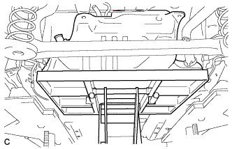
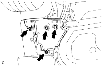
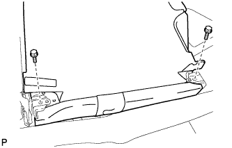
| 8. INSTALL NO. 1 FUEL TANK PROTECTOR SUB-ASSEMBLY |
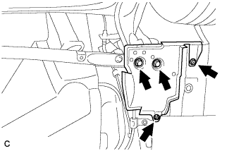
Install the No. 1 fuel tank protector sub-assembly with the 3 bolts and the nut. Tighten the bolts and nut in the following order: bolt 1, bolt 2, bolt 3, and nut 4.
- Момент затяжки:
- 5.5 Н*м{56 кгс*см, 49 фунт-сила-дюймов}
 |
| 9. INSTALL CENTER EXHAUST PIPE ASSEMBLY |
- УКАЗАНИЕ:
- See page Нажмите здесь.
| 10. INSTALL REAR NO. 1 FLOOR UNDER COVER (for Sedan) |
Install the rear No. 1 floor under cover with the 2 grommets.
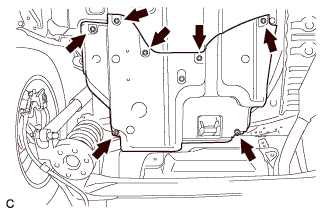 |
Install the 4 clips and nut.
| 11. INSTALL REAR NO. 1 FLOOR UNDER COVER (for Hatchback) |
Install the rear No. 1 floor under cover with the grommet.
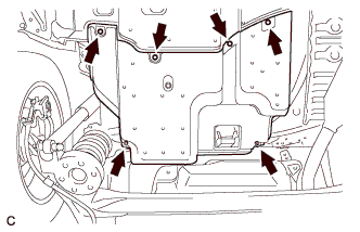 |
Install the 4 clips and nut.
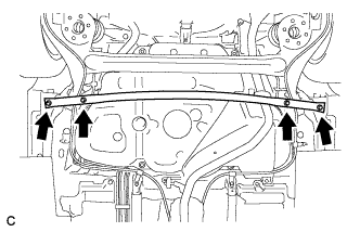
| 12. INSTALL REAR FLOOR SIDE MEMBER BRACE SUB-ASSEMBLY |
Install the rear floor side member brace subassembly with the 4 bolts.
- Момент затяжки:
- 54 Н*м{551 кгс*см, 40 фунт-сила-футов}
 |
| 13. INSTALL REAR FLOOR SIDE MEMBER COVER LH |
Install the rear floor side member cover LH with the nut, grommet and 2 bolts.
- Момент затяжки:
- 5.4 Н*м{55 кгс*см, 48 фунт-сила-дюймов}
 |
| 14. INSTALL REAR FLOOR SIDE MEMBER COVER RH |
Install the rear floor side member cover RH with the nut, grommet and 2 bolts.
- Момент затяжки:
- 5.4 Н*м{55 кгс*см, 48 фунт-сила-дюймов}
 |
| 15. INSPECT FITTING OF FUEL PUMP GAUGE RETAINER |
Inspect the fuel pump gauge retainer.
Install the fuel pump gauge retainer to the fuel tank by hand with the fuel tank vent tube assembly disconnected.
- If the fuel pump gauge retainer can be turned 180° or more by hand, reuse the retainer.
- If the fuel pump gauge retainer cannot be turned 180° or more by hand, use a fuel pump gauge retainer that is available as a supply part.
- УКАЗАНИЕ:
- Check that there is no damage, dent, foreign matter, or other defect on the threads of the fuel tank.
- If the fuel pump gauge retainer can be turned 180° or more by hand, reuse the retainer.
| 16. INSTALL FUEL TANK VENT TUBE ASSEMBLY (for TMC Made) |
Apply a light coat of diesel fuel to a new gasket, and install it to the fuel tank.
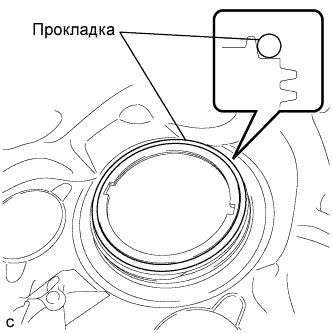 |
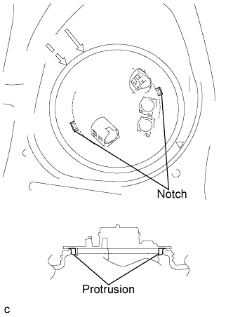
Install the fuel tank vent tube assembly to the fuel tank.
- ПРИМЕЧАНИЕ:
- Make sure that the fuel sender gauge arm does not bend.
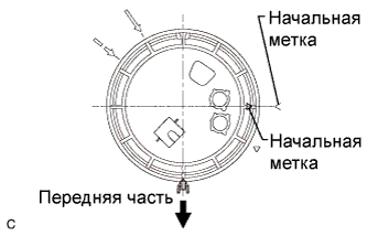
Align the protrusion of the fuel tank vent tube with the notch of the fuel tank.
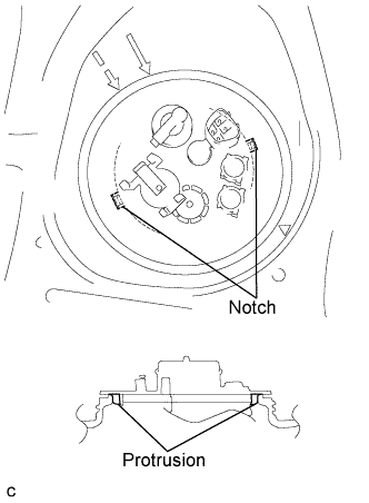 |
While holding the fuel tank vent tube assembly by hand to prevent it from tilting, align the starting marks on the fuel pump gauge retainer and fuel tank and tighten the fuel pump gauge retainer 180° by hand.
- УКАЗАНИЕ:
- Check that there is no damage, dent, foreign matter, or other defect on the threads of the fuel tank.
- The diameter of a supplied fuel pump gauge retainer is larger than that of the factory-installed retainer, anticipating that the fuel tank swells and expands over time. If the diameter of the factoryinstalled retainer is too small to reinstall, use a supplied fuel pump gauge retainer.
 |
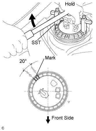
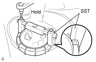
Using a 6 mm socket, set SST to the fuel pump gauge retainer.
- SST
- 09808-14020(09808-01410,09808-01420,09808-01430)
- ПРИМЕЧАНИЕ:
- Do not use any other tools such as a screwdriver.
- УКАЗАНИЕ:
- Insert the notch of SST into the rib of the fuel pump gauge retainer.
- While setting SST, hold the fuel tank vent tube by hand to prevent the gasket from separating from the fuel tank.
 |
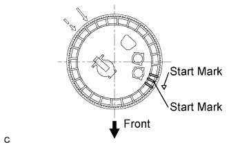
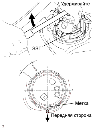
Tighten the fuel pump gauge retainer approximately 360° from the start mark on the fuel tank so that the start mark on the retainer comes within the range shown in the illustration.
- ПРИМЕЧАНИЕ:
- Do not use any other tools such as a screwdriver.
- УКАЗАНИЕ:
- Insert the notch of SST into the rib of the fuel pump gauge retainer.
 |
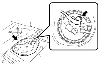
Install the No. 4 fuel tube clamp from the fuel tank vent tube assembly.
 |
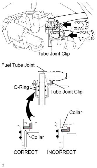
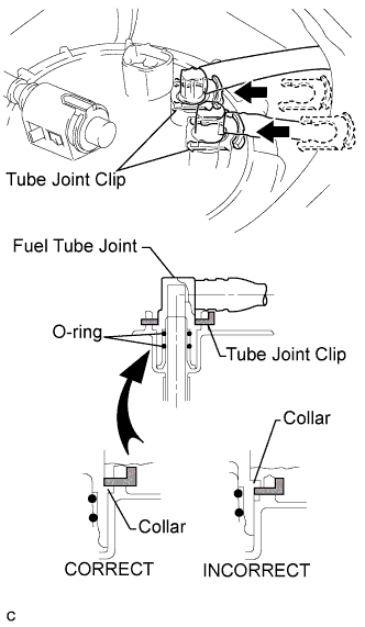
Connect the fuel tank main tube and return tube.
Push the fuel tube joint into the plug of the fuel tank vent tube, then install the 2 tube joint clips.
- ПРИМЕЧАНИЕ:
- Check that there are no scratches or foreign objects on the connecting parts.
- Check that the fuel tube joint is inserted securely.
- Check that the tube joint clips are on the collars of the fuel tube joints.
- After installing the tube joint clips, check that the fuel tube joints have not been pulled off.
- Be careful not to damage any clips. if a clip is damaged, replace it.
| 17. INSTALL FUEL TANK VENT TUBE ASSEMBLY (for TMUK, TMMT Made) |
Apply a light coat of diesel fuel to a new gasket, and install it to the fuel tank.
|
Install the fuel tank vent tube assembly to the fuel tank.
- ПРИМЕЧАНИЕ:
- Make sure that the fuel sender gauge arm does not bend.
Align the protrusion of the fuel tank vent tube with the notch of the fuel tank.
 |
While holding the fuel tank vent tube assembly by hand to prevent it from tilting, align the starting marks on the fuel pump gauge retainer and fuel tank and tighten the fuel pump gauge retainer 180° by hand.
- УКАЗАНИЕ:
- Check that there is no damage, dent, foreign matter, or other defect on the threads of the fuel tank.
- The diameter of a supplied fuel pump gauge retainer is larger than that of the factory-installed retainer, anticipating that the fuel tank swells and expands over time. If the diameter of the factoryinstalled retainer is too small to reinstall, use a supplied fuel pump gauge retainer.
 |
Using a 6 mm socket, set SST to the fuel pump gauge retainer.
- SST
- 09808-14020(09808-01410,09808-01420,09808-01430)
- ПРИМЕЧАНИЕ:
- Do not use any other tools such as a screwdriver.
- УКАЗАНИЕ:
- Insert the notch of SST into the rib of the fuel pump gauge retainer.
- While setting SST, hold the fuel tank vent tube by hand to prevent the gasket from separating from the fuel tank.
 |
Tighten the fuel pump gauge retainer approximately 270° from the start mark on the fuel tank so that the start mark on the retainer comes within the range shown in the illustration.
- ПРИМЕЧАНИЕ:
- Do not use any other tools such as a screwdriver.
- УКАЗАНИЕ:
- Insert the notch of SST into the rib of the fuel pump gauge retainer.
 |
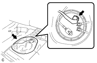
Install the tube.
- ПРИМЕЧАНИЕ:
- Securely install the tube by pushing on it until it makes a clicking sound.
 |
Connect the fuel tank main tube and return tube.
Push the fuel tube joint into the plug of the fuel tank vent tube, then install the 2 tube joint clips.
- ПРИМЕЧАНИЕ:
- Check that there are no scratches or foreign objects on the connecting parts.
- Check that the fuel tube joint is inserted securely.
- Check that the tube joint clips are on the collars of the fuel tube joints.
- After installing the tube joint clips, check that the fuel tube joints have not been pulled off.
- Be careful not to damage any clips. if a clip is damaged, replace it.
| 18. ADD FUEL |
| 19. INSPECT FOR FUEL LEAK |
- УКАЗАНИЕ:
- Using the intelligent tester to perform Active Tests allow relays, VSVs, actuators and other items to be operated without removing any parts. This non-intrusive functional inspection can be very useful because intermittent operation may be discovered before parts or wiring is disturbed. Performing Active Tests early in troubleshooting is one way to save diagnostic time. Data List information can be displayed while performing Active Tests.
- The Data List can be displayed during Active Tests.
Connect an intelligent tester to the DLC3.
Turn the ignition switch to the ON position.
Turn the tester on.
Enter the following menu items: Powertrain / Engine and ECT / Active Test.
Perform the Active Test.
Tester Display Test Part Control Range Diagnostic Notes Active the fuel leak test Pressurize common rail internal fuel pressure, in order to see if fuel leaks ON/OFF - Fuel pressure inside common rail pressurized to 135 MPa and engine speed increased to 2000 rpm when ON selected
- Above conditions preserved while test ON
- Fuel pressure inside common rail pressurized to 135 MPa and engine speed increased to 2000 rpm when ON selected
| 20. INSPECT FOR EXHAUST GAS LEAK |
| 21. INSTALL REAR FLOOR SERVICE HOLE COVER (for TMC Made) |
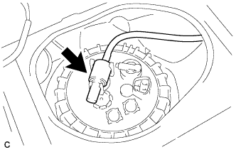
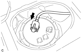
Connect the fuel pump connector.
 |
Install the rear floor service hole cover with new butyl tape.
- ПРИМЕЧАНИЕ:
- Be careful that the rear floor service hole cover does not mount on the protrusions of the floor panel when installing.
Install the floor carpet. (for Hatchback)
| 22. INSTALL REAR FLOOR SERVICE HOLE COVER (for TMUK, TMMT Made) |
Connect the fuel pump connector.
 |
Install the rear floor service hole cover with new butyl tape.
- ПРИМЕЧАНИЕ:
- Be careful that the rear floor service hole cover does not mount on the protrusions of the floor panel when installing.
Install the floor carpet. (for Hatchback)
| 23. INSTALL REAR DOOR SCUFF PLATE RH (for Hatchback) |
- УКАЗАНИЕ:
- See page Нажмите здесь for 5 door
| 24. INSTALL REAR SEAT INNER BELT ASSEMBLY RH (for Hatchback) |
- УКАЗАНИЕ:
- See page Нажмите здесь for TMC made
- See page Нажмите здесь for TMUK, TMMT made
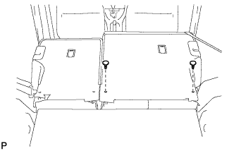
| 25. INSTALL REAR SEAT ASSEMBLY RH (for Hatchback) |
Установите правое заднее сиденье в сборе в салон.
- ПРИМЕЧАНИЕ:
- Соблюдайте осторожность, чтобы не повредить кузов автомобиля.
Закрепите заднюю часть правого заднего сиденья в сборе 2 болтами.
- Момент затяжки:
- Для моделей производства TMC:
- 42 Н*м{428 кгс*см, 31 фунт-сила-футов}
- Для моделей производства TMUK, TMMT:
- 37 Н*м{377 кгс*см, 27 фунт-сила-футов}
 |
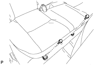
Установите 2 фиксатора.
 |
Закрепите переднюю часть правого заднего сиденья в сборе 2 болтами.
- Момент затяжки:
- Для моделей производства TMC:
- 42 Н*м{428 кгс*см, 31 фунт-сила-футов}
- Для моделей производства TMUK, TMMT:
- 37 Н*м{377 кгс*см, 27 фунт-сила-футов}
 |
| 26. INSTALL NO. 1 REAR SEAT CUSHION HINGE COVER (for Hatchback RH Side) |
- УКАЗАНИЕ:
- See page Нажмите здесь for 5 door
| 27. INSTALL NO. 2 REAR SEAT CUSHION HINGE COVER (for Hatchback RH Side) |
- УКАЗАНИЕ:
- See page Нажмите здесь for 5 door
- See page Нажмите здесь for 3 door
| 28. INSTALL CENTER REAR SEAT HEADREST ASSEMBLY (for Hatchback) |
| 29. INSTALL REAR SEAT HEADREST ASSEMBLY (for Hatchback RH Side) |
| 30. INSTALL REAR DOOR SCUFF PLATE LH (for Hatchback) |
- УКАЗАНИЕ:
- See page Нажмите здесь for 5 door
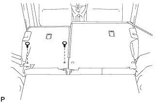
| 31. INSTALL REAR SEAT ASSEMBLY LH (for Hatchback) |
Установите левое заднее сиденье в сборе в салон.
- ПРИМЕЧАНИЕ:
- Соблюдайте осторожность, чтобы не повредить кузов автомобиля.
Закрепите заднюю часть левого заднего сиденья в сборе 2 болтами.
- Момент затяжки:
- Для моделей производства TMC:
- 42 Н*м{428 кгс*см, 31 фунт-сила-футов}
- Для моделей производства TMUK, TMMT:
- 37 Н*м{377 кгс*см, 27 фунт-сила-футов}
 |
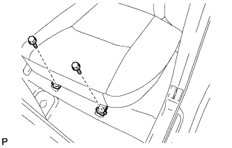
Установите 2 фиксатора.
 |
Закрепите переднюю часть левого заднего сиденья в сборе 2 болтами.
- Момент затяжки:
- Для моделей производства TMC:
- 42 Н*м{428 кгс*см, 31 фунт-сила-футов}
- Для моделей производства TMUK, TMMT:
- 37 Н*м{377 кгс*см, 27 фунт-сила-футов}
 |
| 32. INSTALL NO. 1 REAR SEAT CUSHION HINGE COVER (for Hatchback LH Side) |
- УКАЗАНИЕ:
- See page Нажмите здесь for 5 door
| 33. INSTALL NO. 2 REAR SEAT CUSHION HINGE COVER (for Hatchback LH Side) |
- УКАЗАНИЕ:
- See page Нажмите здесь for 5 door
- See page Нажмите здесь for 3 door
| 34. INSTALL REAR SEAT HEADREST ASSEMBLY (for Hatchback LH Side) |
| 35. INSTALL REAR SEAT CUSHION ASSEMBLY (for Sedan) |
Установите 2 задних крепления подушки сиденья на спинку сиденья.
 |
Закрепите 2 передних крепления подушки сиденья на кузове автомобиля.
Убедитесь, что подушка сиденья установлена надежно.
- ПРИМЕЧАНИЕ:
- При установке подушки сиденья следите за тем, чтобы пряжка ремня безопасности на оказалась под подушкой сиденья.