Топливная Форсунка Снятие. Corolla Auris
Двигатель. COROLLA, AURIS. ZZE150 ZRE151,152 NDE150
DISCONNECT CABLE FROM NEGATIVE BATTERY TERMINAL
DRAIN ENGINE COOLANT
REMOVE NO. 1 ENGINE COVER
REMOVE NO. 1 GLOW PLUG CONNECTOR
SEPARATE OIL LEVEL DIPSTICK GUIDE
REMOVE EGR COOLER ASSEMBLY
REMOVE VACUUM REGULATING VALVE ASSEMBLY
REMOVE NO. 1 INJECTION PIPE CLAMP
REMOVE NO. 2 INJECTION PIPE CLAMP
REMOVE NO. 1 INJECTION PIPE SUB-ASSEMBLY
REMOVE NO. 2 INJECTION PIPE SUB-ASSEMBLY
REMOVE NO. 3 INJECTION PIPE SUB-ASSEMBLY
REMOVE NO. 4 INJECTION PIPE SUB-ASSEMBLY
REMOVE NOZZLE LEAKAGE PIPE ASSEMBLY
REMOVE INJECTOR ASSEMBLY
Топливная Форсунка -- Снятие |
| 1. DISCONNECT CABLE FROM NEGATIVE BATTERY TERMINAL |
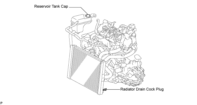
Loosen the radiator drain cock plug.
- УКАЗАНИЕ:
- Collect the coolant in a container and dispose of it according to the regulations in your area.
Remove the radiator reservoir cap.
- ПРЕДОСТЕРЕЖЕНИЕ:
- Do not remove the radiator reservoir cap while the engine and radiator are still hot.
- Pressurized, hot engine coolant and steam may be released and cause serious burns.
Loosen the cylinder block drain cock plug.
- УКАЗАНИЕ:
- The plug is on the backside of the generator on the exhaust manifold side.
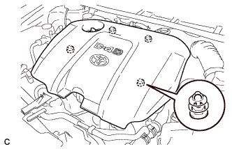
| 3. REMOVE NO. 1 ENGINE COVER |
Disengage the 4 pins and remove No. 1 engine cover sub-assembly.
| 4. REMOVE NO. 1 GLOW PLUG CONNECTOR |
Remove the 5 screw grommets.
Remove the nut and disconnect the glow terminal.
Remove the 4 nuts and No. 1 glow plug connector.
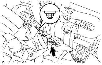
| 5. SEPARATE OIL LEVEL DIPSTICK GUIDE |
Remove the bolt and separate the oil level dipstick guide.
| 6. REMOVE EGR COOLER ASSEMBLY |
Disconnect the 2 water by-pass hoses.
Remove the bolt and 4 nuts, then remove the EGR cooler assembly.
Remove the 2 gaskets.
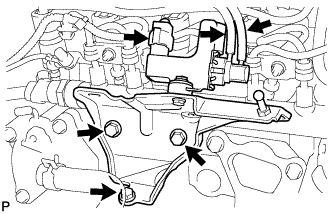
| 7. REMOVE VACUUM REGULATING VALVE ASSEMBLY |
Disconnect the connector clamp and connector.
Disengage the 2 hose clamps and disconnect the 2 vacuum hoses.
Remove the 3 bolts, then remove the vacuum regulating valve together with the bracket.
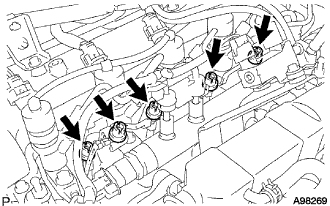
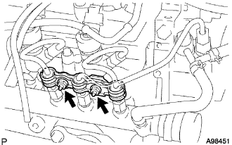
| 8. REMOVE NO. 1 INJECTION PIPE CLAMP |
Remove the 2 nuts, then remove the No. 1 injection pipe clamp.
| 9. REMOVE NO. 2 INJECTION PIPE CLAMP |
Remove the nut, then remove the No. 2 injection pipe clamp.
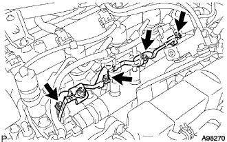
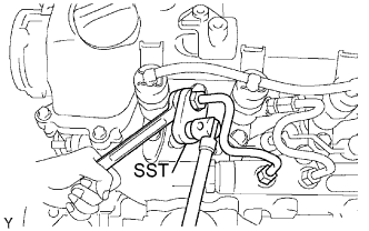
| 10. REMOVE NO. 1 INJECTION PIPE SUB-ASSEMBLY |
Using a wrench (13 mm), hold the injector steadily, and using SST, remove the injection pipe from the injector side.
- SST
- 09023-38401
Using SST, remove the injection pipe from the common rail side.
- SST
- 09023-38401
After removing the injection pipe, cover the common rail with vinyl tape and cover the injector inlet with a vinyl or plastic bag in order to prevent dust and foreign matter from entering.
| 11. REMOVE NO. 2 INJECTION PIPE SUB-ASSEMBLY |
- SST
- 09023-38401
- УКАЗАНИЕ:
- Perform the same procedure as for the No. 1 injection pipe.
| 12. REMOVE NO. 3 INJECTION PIPE SUB-ASSEMBLY |
- SST
- 09023-38401
- УКАЗАНИЕ:
- Perform the same procedure as for the No. 1 injection pipe.
| 13. REMOVE NO. 4 INJECTION PIPE SUB-ASSEMBLY |
- SST
- 09023-38401
- УКАЗАНИЕ:
- Perform the same procedure as for the No. 1 injection pipe.
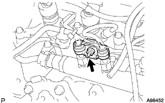
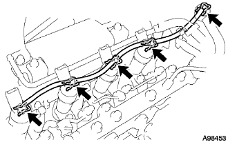
| 14. REMOVE NOZZLE LEAKAGE PIPE ASSEMBLY |
Remove the 5 retainer springs, then remove the nozzle leakage pipe.
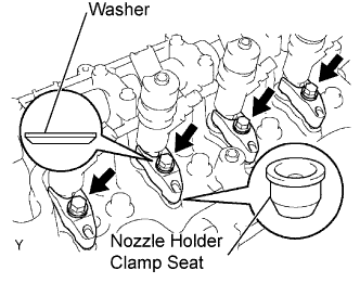
| 15. REMOVE INJECTOR ASSEMBLY |
- УКАЗАНИЕ:
- Each injector assembly has its own serial number. When replacing the injector assembly, store them in the correct order so that they can be returned to their original locations when reassembled.
- Arrange the injectors, clamps, washers, bolts and clamp seats in the correct order.
Remove the 4 bolts, 4 washers, 4 nozzle holder clamps and 4 nozzle holder clamp seats.
Disconnect the 4 injector connectors.
Remove the 4 injectors from the cylinder head.
Remove the 4 injection nozzle seats from the injector or cylinder head.
- ПРИМЕЧАНИЕ:
- When removing the injector, check that the injector nozzle seat is either attached to the injector, or remains in the cylinder head.