Dtc P0340 Camshaft Position Sensor A Circuit (Bank 1 Or Single Sensor). Corolla Auris
Двигатель. COROLLA, AURIS. ZZE150 ZRE151,152 NDE150
DESCRIPTION
WIRING DIAGRAM
INSPECTION PROCEDURE
INSPECT CAMSHAFT POSITION SENSOR (POWER SOURCE VOLTAGE)
CHECK HARNESS AND CONNECTOR (CAMSHAFT POSITION SENSOR - ECM)
CHECK SENSOR INSTALLATION (CAMSHAFT POSITION SENSOR)
CHECK CAMSHAFT TIMING GEAR OR SPROCKET
REPLACE CAMSHAFT POSITION SENSOR
CHECK WHETHER DTC OUTPUT RECURS (P0340)
ADJUST VALVE TIMING
CHECK WHETHER DTC OUTPUT RECURS (DTCS P0340)
CHECK FUSE (EFI NO. 2 FUSE)
DTC P0340 Camshaft Position Sensor "A" Circuit (Bank 1 or Single Sensor) |
DESCRIPTION
The camshaft position sensor is installed on the cylinder head. The sensor plate has one tooth on its circumference, and is installed on the camshaft timing pulley. When the camshaft rotates, the tooth on the camshaft timing pulley passes through the crankshaft position sensor. The generated voltage in the sensor acts as a signal. The ECM determines each cylinder position based on the combination of this signal and crankshaft position sensor output.DTC No.
| DTC Detection Condition
| Trouble Area
|
P0340
| No camshaft position sensor signal is set to ECM while cranking
(The MIL is illuminated and a DTC is immediately set when a malfunction is detected)
| - Open or short in camshaft position sensor circuit
- Camshaft position sensor
- Camshaft timing gear or sprocket
- ECM
|
WIRING DIAGRAM
Refer to DTC P0335 (See page Нажмите здесь).
INSPECTION PROCEDURE
- УКАЗАНИЕ:
- Read freeze frame data using an intelligent tester. The ECM records vehicle and driving condition information as freeze frame data the moment a DTC is stored. When troubleshooting, freeze frame data can be helpful in determining whether the vehicle was running or stopped, whether the engine was warmed up or not, whether the air fuel ratio was lean or rich, as well as other data recorded at the time of a malfunction.
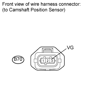
| 1.INSPECT CAMSHAFT POSITION SENSOR (POWER SOURCE VOLTAGE) |
Disconnect the camshaft position sensor connector.
Turn the ignition switch to the ON position.
Measure the voltage according to the value(s) in the table below.
- Standard voltage:
Tester Connection
| Switch Condition
| Specified Condition
|
B70-3 (VG) - Body ground
| Ignition switch ON
| 9 to 14 V
|
Reconnect the camshaft position sensor connector.
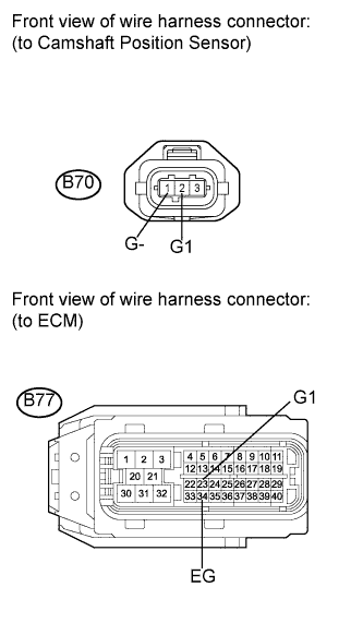
| 2.CHECK HARNESS AND CONNECTOR (CAMSHAFT POSITION SENSOR - ECM) |
Disconnect the camshaft position sensor connector.
Disconnect the ECM connector.
Measure the resistance according to the value(s) in the table below.
- Standard resistance (Check for open):
Tester Connection
| Condition
| Specified Condition
|
B70-2 (G1) - B77-23 (G1)
| Always
| Below 1 Ω
|
B70-1 (G-) - B77-34 (EG)
| Always
| Below 1 Ω
|
- Standard resistance (Check for short):
Tester Connection
| Condition
| Specified Condition
|
B70-2 (G1) or B77-23 (G1) - Body ground
| Always
| 10 kΩ or higher
|
B70-1 (G-) or B77-34 (EG) - Body ground
| Always
| 10 kΩ or higher
|
Reconnect the camshaft position sensor connector.
Reconnect the ECM connector.
| | REPAIR OR REPLACE HARNESS OR CONNECTOR (CAMSHAFT POSITION SENSOR - ECM) |
|
|
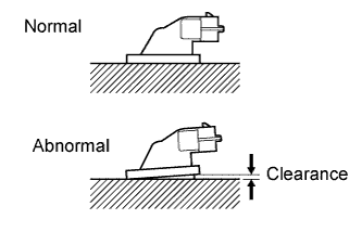
| 3.CHECK SENSOR INSTALLATION (CAMSHAFT POSITION SENSOR) |
Check the camshaft position sensor installation.
- OK:
- The sensor is installed correctly.
| 4.CHECK CAMSHAFT TIMING GEAR OR SPROCKET |
Check the teeth of the camshaft timing gear or sprocket.
- OK:
- The teeth do not have any cracks or deformation.
| 5.REPLACE CAMSHAFT POSITION SENSOR |
Replace camshaft position sensor (See page Нажмите здесь).
| 6.CHECK WHETHER DTC OUTPUT RECURS (P0340) |
Connect the intelligent tester to the DLC3.
Turn the ignition switch to the ON position.
Turn the tester on.
Clear the DTCs (See page Нажмите здесь).
Start the engine.
Enter the following menu items: Powertrain / Engine and ECT / DTC.
Read the DTCs.
- Result:
Result
| Proceed to
|
DTC is not output
| A
|
DTC P0340 is output
| B
|
Adjust the valve timing (See page Нажмите здесь).
| 8.CHECK WHETHER DTC OUTPUT RECURS (DTCS P0340) |
Connect the intelligent tester to the DLC3.
Turn the ignition switch to the ON position.
Turn the tester on.
Clear the DTCs (See page Нажмите здесь).
Start the engine.
Enter the following menu items: Powertrain / Engine and ECT / DTC.
Read the DTCs.
- Result:
Result
| Proceed to
|
DTC is not output
| A
|
DTC P0340 is output
| B
|
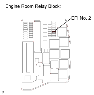
| 9.CHECK FUSE (EFI NO. 2 FUSE) |
Remove the EFI No. 2 fuse from the engine room relay block.
Measure the resistance according to the value(s) in the table below.
- Standard resistance:
Tester Connection
| Condition
| Specified Condition
|
EFI No. 2 fuse
| Always
| Below 1 Ω
|
Reinstall the EFI No. 2 fuse.
| | REPLACE FUSE (EFI NO. 2 FUSE) |
|
|
| OK |
|
|
|
| REPAIR OR REPLACE HARNESS OR CONNECTOR (CAMSHAFT POSITION SENSOR - EFI MAIN RELAY) |
|