Land Cruiser URJ200 URJ202 GRJ200 VDJ200 - JF2A TRANSFER / 4WD / AWD
TRANSFER ASSEMBLY - INSPECTION
| 1. INSPECT TRANSFER INPUT SHAFT |
Using a micrometer, measure the diameter of the input shaft journal surface.
- Minimum Diameter:
- 68 mm (2.68 in.)
If the diameter is less than the minimum, replace the input shaft.
Using a dial indicator, measure the inside diameter of the input shaft bush.
- Maximum Inside Diameter:
- 46 mm (1.81 in.)
If the inside diameter is more than the maximum, replace the input shaft.
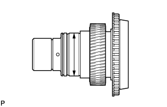
| 2. INSPECT TRANSFER LOW PLANETARY GEAR ASSEMBLY |

Using a feeler gauge, measure the thrust clearance of the pinion gear.
- Standard Clearance:
- 0.11 to 0.85 mm (0.00434 to 0.0334 in.)
- Maximum Clearance:
- 0.85 mm (0.0334 in.)
If the clearance is more than the maximum, replace the low planetary gear assembly.
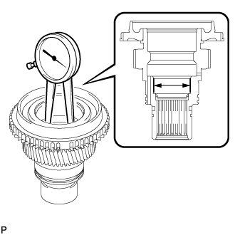
Using a dial indicator, measure the radial clearance of the pinion gear.
- Standard Clearance:
- 0.01 to 0.04 mm (0.000434 to 0.00150 in.)
- Maximum Clearance:
- 0.04 mm (0.00150 in.)
If the clearance is more than the maximum, replace the low planetary gear assembly.
| 3. INSPECT REAR TRANSFER OUTPUT SHAFT |

Using a micrometer, measure the diameter of the output shaft journals.
- Minimum Diameter:
Journal Specified Condition A 38 mm (1.50 in.) B 42 mm (1.65 in.) C 49 mm (1.93 in.)
If the diameter is less than the minimum, replace the output shaft.
| 4. INSPECT NO. 1 TRANSFER GEAR SHIFT FORK AND FRONT DRIVE CLUTCH SLEEVE |
Using a feeler gauge, measure the clearance between the clutch sleeve and gear shift fork.
- Maximum Clearance:
- 0.8 mm (0.0315 in.)
If the clearance is more than the maximum, replace the clutch sleeve or shift fork.
| 5. INSPECT NO. 2 TRANSFER GEAR SHIFT FORK AND HIGH AND LOW CLUTCH SLEEVE |

Using a feeler gauge, measure the clearance between the clutch sleeve and gear shift fork.
- Maximum Clearance:
- 3.15 mm (0.124 in.)
If the clearance is more than the maximum, replace the clutch sleeve or shift fork.
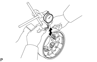
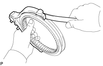
| 6. INSPECT NO. 1 SYNCHRONIZER RING (for Manual Transmission) |
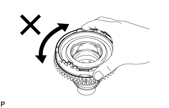
Apply gear oil to the cone of the input shaft, and check that it does not turn in both directions while pushing the No. 1 synchronizer ring.
If it can turn, replace the No. 1 synchronizer ring.
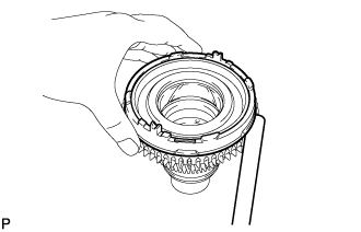
Push the No. 1 synchronizer ring to the cone of the input shaft. Measure the clearance between the No. 1 synchronizer ring and input shaft.
- Standard Clearance:
- 0.86 to 1.54 mm (0.0339 to 0.0606 in.)
- Minimum Clearance:
- 0.86 mm (0.0339 in.)
If the clearance is not as specified, replace the No. 1 synchronizer ring with a new one.