Land Cruiser URJ200 URJ202 GRJ200 VDJ200 - JF2A TRANSFER / 4WD / AWD
TRANSFER SYSTEM - INSPECTION
| 1. INSPECT INDICATOR LIGHT |
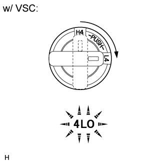
Check the 4LO indicator light.
Start the engine.
Stop the vehicle.
for Automatic Transmission: Move the shift lever to N.
for Manual Transmission: Depress the clutch pedal.
Turn the transfer position switch from H4 to L4.
Check the 4LO indicator light.
- OK:
Switch Condition Specified Condition Turned from H4 to L4 4LO indicator light comes on immediately or comes on after blinking

- OK:
Switch Condition Specified Condition Turned from H4 to L4 4LO indicator light and center differential lock indicator light come on immediately or come on after blinking
- HINT:
- For vehicles without VSC (Vehicle Stability Control), when the transfer position switch is turned from H4 to L4, the center differential will lock.
Check the center differential lock indicator light.
Start the engine.
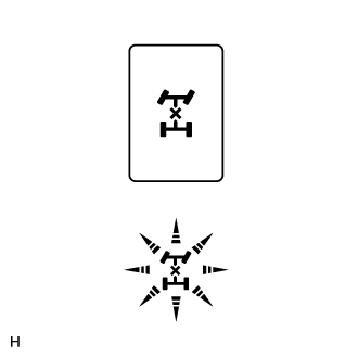
Push the center differential lock switch.
- NOTICE:
Check the center differential lock indicator light.
- OK:
Switch Condition Specified Condition Pushed Center differential lock indicator light comes on immediately or comes on after blinking
If there is a malfunction, inspect the switch, ECU and transfer shift actuator. If the system is normal, there may be a malfunction in the CAN communication system or combination meter. In that case, first check the CAN communication system for LHD (), for RHD (). Then check the combination meter ().
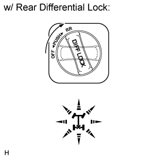
w/ Rear Differential Lock:
Check the rear differential lock indicator light.
Start the engine.
Stop the vehicle.
for Automatic Transmission: Move the shift lever to N.
for Manual Transmission: Depress the clutch pedal.
Turn the transfer position switch from H4 to L4.
- HINT:
- The rear differential can be locked only when the following conditions are met: 1) The transfer is in low, and 2) the center differential is locked. As vehicles with a rear differential lock do not have a vehicle stability control system, these conditions will be satisfied after the transfer position switch is turned to L4, the transfer shifts to low, and the center differential locks.
Turn the differential lock switch from OFF to RR.
- NOTICE:
- When locking the rear differential, make sure that the vehicle speed is less than 8 km/h (5 mph).
Check the rear differential lock indicator light.
- OK:
Switch Condition Specified Condition After transfer position switch is turned from H4 to L4, differential lock switch is turned from OFF to RR Rear differential lock indicator light comes on immediately or comes on after blinking
If there is a malfunction, inspect the switch, ECU and differential lock shift actuator.
- HINT:
| 2. INSPECT FUSE |
Remove the 4WD fuse from the main body ECU (cowl side junction block LH).
Measure the resistance according to the value(s) in the table below.
- Standard Resistance:
Tester Connection Condition Specified Condition 4WD fuse Always Below 1 Ω
If a fuse is blown, inspect the harness connected to the fuse for a short circuit, and repair or replace the harness or replace the fuse.
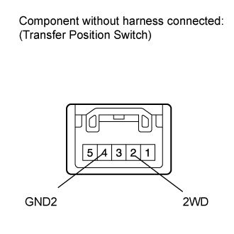
| 3. INSPECT TRANSFER POSITION SWITCH |
Remove the transfer position switch ().
Measure the resistance according to the value(s) in the table below.
- Standard Resistance:
Tester Connection Switch Condition Specified Condition 2 (2WD) - 4 (GND2) H4 position 100 kΩ or higher L4 position Below 1 Ω
If there is a malfunction, replace the transfer position switch.
Check the harness and connector (ECU - transfer position switch and body ground).
Disconnect the A27 ECU connector.
Disconnect the E48 transfer position switch connector.
Measure the resistance according to the value(s) in the table below.
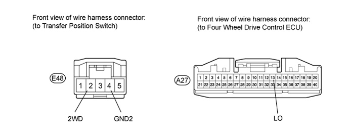
- Standard Resistance:
Tester Connection Condition Specified Condition E48-2 (2WD) - A27-13 (LO) Always Below 1 Ω E48-2 (2WD) - Body ground Always 100 kΩ or higher E48-4 (GND2) - Body ground Always Below 1 Ω
If there is a malfunction, repair or replace the harness or connector.
| 4. INSPECT CENTER DIFFERENTIAL LOCK SWITCH |
Remove the center differential lock switch ().
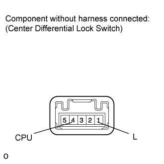
Measure the resistance according to the value(s) in the table below.
- Standard Resistance:
Tester Connection Switch Condition Specified Condition 1 (L) - 4 (CPU) Switch is pressed and held Below 1 Ω Switch is not pressed 100 kΩ or higher
If there is a malfunction, replace the center differential lock switch.
Check the harness and connector (ECU - center differential lock switch and body ground).
Disconnect the ECU connector.
Disconnect the center differential lock switch connector.
Measure the resistance according to the value(s) in the table below.
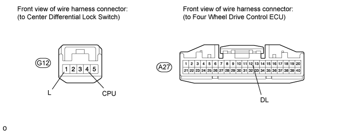
- Standard Resistance:
Tester Connection Condition Specified Condition A27-12 (DL) - G12-4 (CPU) Always Below 1 Ω A27-12 (DL) - Body ground Always 100 kΩ or higher G12-1 (L) - Body ground Always Below 1 Ω
If there is a malfunction, repair or replace the harness or connector.
| 5. INSPECT DIFFERENTIAL LOCK SWITCH (w/ Rear Differential Lock) |
Remove the differential lock switch ().

Measure the resistance according to the value(s) in the table below.
- Standard Resistance:
Tester Connection Switch Condition Specified Condition 1 (IG) - 4 (R) OFF 10 kΩ or higher RR Below 1 Ω
If there is a malfunction, replace the differential lock switch.
Check the harness and connector (ECU - differential lock switch and body ground).
Disconnect the A27 ECU connector.
Disconnect the E87 differential lock switch connector.
Measure the resistance according to the value(s) in the table below.
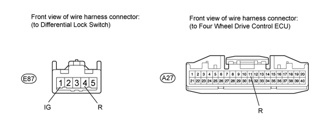
- Standard Resistance:
Tester Connection Condition Specified Condition A27-11 (R) - E87-1 (IG) Always Below 1 Ω A27-11 (R) - Body ground Always 100 kΩ or higher E87-4 (R) - Body ground Always Below 1 Ω
If there is a malfunction, repair or replace the harness or connector.
| 6. INSPECT TRANSFER SHIFT ACTUATOR ASSEMBLY (HIGH-LOW TRANSFER SHIFT ACTUATOR) |
- HINT:
- After inspecting the ECU power supply or transfer position switch, check the high-low transfer shift actuator.
Check the harness and connector (ECU - high-low transfer shift actuator).
Disconnect the C38 actuator connector.
Disconnect the A27 and A28 ECU connectors.
Measure the resistance according to the value(s) in the table below.

- Standard Resistance:
Tester Connection Condition Specified Condition A27-1 (HL1) - C38-4 (HL1) Always Below 1 Ω A27-1 (HL1) - Body ground Always 100 kΩ or higher A27-2 (HL2) - C38-6 (HL2) Always Below 1 Ω A27-2 (HL2) - Body ground Always 100 kΩ or higher A27-3 (HL3) - C38-5 (HL3) Always Below 1 Ω A27-3 (HL3) - Body ground Always 100 kΩ or higher A27-16 (NP) - C38-3 (N) Always Below 1 Ω A27-16 (NP) - Body ground Always 100 kΩ or higher A28-2 (HM1) - C38-1 (HM1) Always Below 1 Ω A28-2 (HM1) - Body ground Always 100 kΩ or higher A28-6 (HM2) - C38-2 (HM2) Always Below 1 Ω A28-6 (HM2) - Body ground Always 100 kΩ or higher C38-7 (GND) - Body ground Always Below 1 Ω
If there is a malfunction, repair or replace the harness or connector.
Check the high-low transfer shift actuator.
Turn the engine switch on (IG).
Stop the vehicle.
for Automatic Transmission: Move the shift lever to N.
for Manual Transmission: Depress the clutch pedal.
Check that there is an operating noise from the transfer shift actuator when the transfer position switch is turned from H4 to L4, or L4 to H4.
- OK:
- There is an operating noise.
- HINT:
Remove the transfer shift actuator assembly ().
Check the high to low switch.
- NOTICE:
- HINT:
- When performing the operation described above, use the DEFOG relay.

- Standard Resistance:
Tester Connection Condition Specified Condition 3 (N) - 7 (GND) After high to low switch is complete 100 kΩ or higher 4 (HL1) - 7 (GND) After high to low switch is complete 100 kΩ or higher 5 (HL3) - 7 (GND) After high to low switch is complete 100 kΩ or higher 6 (HL2) - 7 (GND) After high to low switch is complete Below 1 Ω
Check the low to high switch.
- NOTICE:
- HINT:
- When performing the operation described above, use the DEFOG relay.

- Standard Resistance:
Tester Connection Condition Specified Condition 3 (N) - 7 (GND) After low to high switch is complete 100 kΩ or higher 4 (HL1) - 7 (GND) After low to high switch is complete Below 1 Ω 5 (HL3) - 7 (GND) After low to high switch is complete 100 kΩ or higher 6 (HL2) - 7 (GND) After low to high switch is complete 100 kΩ or higher
| 7. INSPECT TRANSFER SHIFT ACTUATOR ASSEMBLY (CENTER DIFFERENTIAL LOCK ACTUATOR) |
- HINT:
- After inspecting the ECU power supply or center differential lock switch, inspect the center differential lock actuator.
Check the harness and connector (ECU - center differential lock actuator).
Disconnect the C37 actuator connector.
Disconnect the A27 and A28 ECU connectors.
Measure the resistance according to the value(s) in the table below.
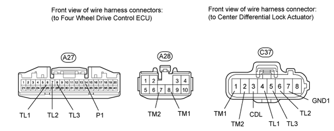
- Standard Resistance:
Tester Connection Condition Specified Condition A27-6 (TL1) - C37-4 (TL1) Always Below 1 Ω A27-6 (TL1) - Body ground Always 100 kΩ or higher A27-7 (TL2) - C37-6 (TL2) Always Below 1 Ω A27-7 (TL2) - Body ground Always 100 kΩ or higher A27-8 (TL3) - C37-5 (TL3) Always Below 1 Ω A27-8 (TL3) - Body ground Always 100 kΩ or higher A27-14 (P1) - C37-3 (CDL) Always Below 1 Ω A27-14 (P1) - Body ground Always 100 kΩ or higher A28-7 (TM2) - C37-2 (TM2) Always Below 1 Ω A28-7 (TM2) - Body ground Always 100 kΩ or higher A28-8 (TM1) - C37-1 (TM1) Always Below 1 Ω A28-8 (TM1) - Body ground Always 100 kΩ or higher C37-7 (GND) - Body ground Always Below 1 Ω
If there is a malfunction, repair or replace the harness or connector.
Check the center differential lock actuator.
Turn the engine switch on (IG).
Check that there is an operating noise from the transfer shift actuator when the center differential lock switch is pressed to switch from free to lock, or lock to free.
- OK:
- There is an operating noise.
- HINT:
Remove the transfer shift actuator assembly ().
Check the free to lock switch.
- NOTICE:
- HINT:
- When performing the operation described above, use the DEFOG relay.
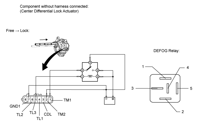
- Standard Resistance:
Tester Connection Condition Specified Condition 3 (CDL) - 7 (GND1) After free to lock switch is complete Below 1 Ω 4 (TL1) - 7 (GND1) After free to lock switch is complete 100 kΩ or higher 5 (TL3) - 7 (GND) After free to lock switch is complete 100 kΩ or higher 6 (TL2) - 7 (GND1) After free to lock switch is complete Below 1 Ω
Check the lock to free switch.
- NOTICE:
- HINT:
- When performing the operation described above, use the DEFOG relay.

- Standard Resistance:
Tester Connection Condition Specified Condition 3 (CDL) - 7 (GND1) After lock to free switch is complete 100 kΩ or higher 4 (TL1) - 7 (GND1) After lock to free switch is complete 100 kΩ or higher 5 (TL3) - 7 (GND1) After lock to free switch is complete Below 1 Ω 6 (TL2) - 7 (GND1) After lock to free switch is complete 100 kΩ or higher
| 8. INSPECT DIFFERENTIAL LOCK SHIFT ACTUATOR (w/ Rear Differential Lock) |
- HINT:
- After inspecting the transfer position switch, transfer shift actuator and differential lock switch, check the differential lock shift actuator.
Check the harness and connector (ECU - differential lock shift actuator).
Disconnect the f1 actuator connector.
Disconnect the A27 and A28 ECU connectors.
Measure the resistance according to the value(s) in the table below.
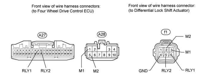
- Standard Resistance:
Tester Connection Condition Specified Condition A27-9 (RLY1) - f1-6 (RLY1) Always Below 1 Ω A27-9 (RLY1) - Body ground Always 100 kΩ or higher A27-10 (RLY2) - f1-5 (RLY2) Always Below 1 Ω A27-10 (RLY2) - Body ground Always 100 kΩ or higher A28-1 (M1) - f1-3 (M1) Always Below 1 Ω A28-1 (M1) - Body ground Always 100 kΩ or higher A28-5 (M2) - f1-2 (M2) Always Below 1 Ω A28-5 (M2) - Body ground Always 100 kΩ or higher f1-4 (GND) - Body ground Always Below 1 Ω
If there is a malfunction, repair or replace the harness or connector.
Check the harness and connector (ECU - differential lock position switch).
Disconnect the f2 differential lock position switch connector.
Disconnect the A27 ECU connector.
Measure the resistance according to the value(s) in the table below.
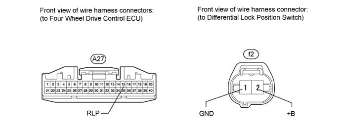
- Standard Resistance:
Tester Connection Condition Specified Condition A27-15 (RLP) - f2-2 (+B) Always Below 1 Ω A27-15 (RLP) - Body ground Always 100 kΩ or higher f2-1 (GND) - Body ground Always Below 1 Ω
If there is a malfunction, repair or replace the harness or connector.
Check the differential lock shift actuator.
Turn the engine switch on (IG).
Check that there is an operating noise from the differential lock shift actuator when the differential lock switch is switch from OFF to RR (free to lock), or RR to OFF (lock to free).
- NOTICE:
- HINT:
- Perform this operation when the transfer is in low and the center differential is locked.
- OK:
- There is an operating noise.
- HINT:
Remove the differential lock shift actuator assembly ().
Check the free to lock switch.
- NOTICE:
- HINT:
- When performing the operation described above, use the DEFOG relay.
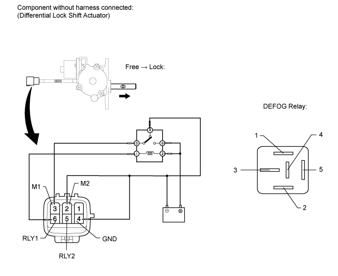
- Standard Resistance:
Tester Connection Condition Specified Condition 5 (RLY2) - 4 (GND) After free to lock switch is complete Below 12.5 Ω 6 (RLY1) - 4 (GND) After free to lock switch is complete 500 kΩ or higher
Check the lock to free switch.
- NOTICE:
- HINT:
- When performing the operation described above, use the DEFOG relay.

- Standard Resistance:
Tester Connection Condition Specified Condition 5 (RLY2) - 4 (GND) After lock to free switch is complete 500 kΩ or higher 6 (RLY1) - 4 (GND) After lock to free switch is complete Below 12.5 Ω
Inspect the rear differential lock position switch.
Remove the rear differential lock position switch ().
Measure the resistance according to the value(s) in the table below.

- Standard Resistance:
Tester Connection Switch Condition Specified Condition 2 (+B) - 1 (GND) Pushed Below 1 Ω Not pushed 100 kΩ or higher
If there is a malfunction, replace the rear differential lock position switch.
| 9. INSPECT 4 WHEEL DRIVE CONTROL ECU |
Check the four wheel drive control ECU.
Measure the resistance and voltage according to the value(s) in the table below.
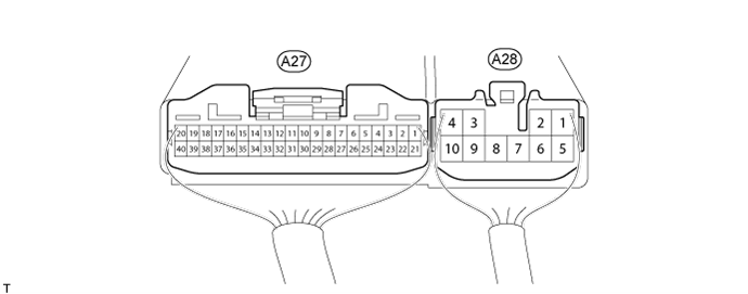
| Tester Connection | Terminal Description | Condition | Specified Condition |
| A27-1 (HL1) - A28-4 (GND) | High-low transfer shift actuator limit switch | Engine switch on (IG) Transfer in high position | Below 1.5 V |
| Engine switch on (IG) Transfer in low position | 11 to 14 V | ||
| Engine switch on (IG) Transfer in neutral position | 11 to 14 V | ||
| A27-2 (HL2) - A28-4 (GND) | High-low transfer shift actuator limit switch | Engine switch on (IG) Transfer in high position | 11 to 14 V |
| Engine switch on (IG) Transfer in low position | Below 1.5 V | ||
| Engine switch on (IG) Transfer in neutral position | 11 to 14 V | ||
| A27-3 (HL3) - A28-4 (GND) | High-low transfer shift actuator limit switch | Engine switch on (IG) Transfer in high position | 11 to 14 V |
| Engine switch on (IG) Transfer in low position | 11 to 14 V | ||
| Engine switch on (IG) Transfer in neutral position | Below 1.5 V | ||
| A27-5 (TT) - A27-25 (TGND)*1 | Temperature sensor | Engine switch on (IG) | 0 to 5 V |
| A27-6 (TL1) - A28-4 (GND) | Center differential lock actuator limit switch | Engine switch on (IG) Center differential in free position | 11 to 14 V |
| Engine switch on (IG) Center differential in lock position | 11 to 14 V | ||
| Engine switch on (IG) Transfer in neutral position | Below 1.5 V | ||
| A27-7 (TL2) - A28-4 (GND) | Center differential lock actuator limit switch | Engine switch on (IG) Center differential in free position | 11 to 14 V |
| Engine switch on (IG) Center differential in lock position | Below 1.5 V | ||
| Engine switch on (IG) Transfer in neutral position | 11 to 14 V | ||
| A27-8 (TL3) - A28-4 (GND) | Center differential lock actuator limit switch | Engine switch on (IG) Center differential in free position | Below 1.5 V |
| Engine switch on (IG) Center differential in lock position | 11 to 14 V | ||
| Engine switch on (IG) Transfer in neutral position | 11 to 14 V | ||
| A27-9 (RLY1) - A28-4 (GND)*2 | Differential lock shift actuator limit switch | Engine switch on (IG) Rear differential in free position | Below 0.5 V |
| Engine switch on (IG) Rear differential in lock position | 11 to 14 V | ||
| A27-10 (RLY2) - A28-4 (GND)*2 | Differential lock shift actuator limit switch | Engine switch on (IG) Rear differential in free position | 11 to 14 V |
| Engine switch on (IG) Rear differential in lock position | Below 0.5 V | ||
| A27-11 (R) - A28-4 (GND)*2 | Differential lock switch | Engine switch on (IG) Differential lock switch in OFF position | 11 to 14 V |
| Engine switch on (IG) Differential lock switch in RR position | Below 1.5 V | ||
| A27-12 (DL) - A28-4 (GND) | Transfer position switch | Engine switch on (IG) Transfer in high position | 11 to 14 V |
| Engine switch on (IG) Transfer in low position | Below 1.5 V | ||
| A27-13 (LO) - A28-4 (GND) | Center differential lock switch | Engine switch on (IG) Center differential lock switch pressed and held | Below 1.5 V |
| Engine switch on (IG) Center differential lock switch not pressed | 11 to 14 V | ||
| A27-14 (P1) - A28-4 (GND) | Center differential lock detection switch | Engine switch on (IG) Center differential in free position | 11 to 14 V |
| Engine switch on (IG) Center differential in lock position | Below 1.5 V | ||
| A27-15 (RLP) - A28-4 (GND)*2 | Rear differential lock position switch | Engine switch on (IG) Rear differential in free position | 11 to 14 V |
| Engine switch on (IG) Rear differential in lock position | Below 1.5 V | ||
| A27-16 (NP) - A28-4 (GND) | Transfer shift actuator neutral position detection switch | Engine switch on (IG) Transfer in neutral position | Below 1.5 V |
| Engine switch on (IG) Transfer in high or low position | 11 to 14 V | ||
| A27-17 (MTN) - A28-4 (GND)*3 | Clutch start switch | Engine switch on (IG) Clutch pedal released | 11 to 14 V |
| Engine switch on (IG) Clutch pedal depressed | Below 2 V | ||
| A27-19 (CAN+) - A27-20 (CAN-) | CAN communication line | Engine switch off | 54 to 69 Ω |
| A27-21 (L4) - A28-4 (GND) | Transfer shift actuator Low detection switch | Transfer position switch in H4 position | 11 to 14 V |
| Engine switch on (IG) Transfer position switch in L4 position | Below 1.5 V | ||
| A28-1 (M1) - A28-4 (GND)*2 | Differential lock shift actuator motor | Engine switch on (IG) Transfer in low position Center differential in lock position Differential lock switch OFF → RR (During operation of differential lock shift actuator motor from free to lock) | 11 to 14 V |
| Engine switch on (IG) Transfer in low position Center differential in lock position Differential lock switch RR → OFF or transfer position switch L4 → H4 (During operation of differential lock shift actuator motor from lock to free) | Below 1.5 V | ||
| A28-2 (HM1) - A28-4 (GND) | High-low transfer shift actuator motor | Engine switch on (IG) Transfer position switch H4 → L4 (During operation of high-low transfer shift actuator motor from high to low) | Below 1.5 V or alternating between below 1.5 V and 11 to 14 V |
| Engine switch on (IG) Transfer position switch L4 → H4 (During operation of high-low transfer shift actuator motor from low to high) | 11 to 14 V | ||
| A28-3 (IG) - A28-4 (GND) | IG power | Engine switch on (IG) | 11 to 14 V |
| A28-4 (GND) - Body ground | Ground | Always | Below 1 Ω |
| A28-5 (M2) - A28-4 (GND)*2 | Differential lock shift actuator motor | Engine switch on (IG) Transfer in low position Center differential in lock position Differential lock switch OFF → RR (During operation of differential lock shift actuator motor from free to lock) | Below 1.5 V |
| Engine switch on (IG) Transfer in low position Center differential in lock position Differential lock switch RR → OFF or transfer position switch L4 → H4 (During operation of differential lock shift actuator motor from lock to free) | 11 to 14 V | ||
| A28-6 (HM2) - A28-4 (GND) | High-low transfer shift actuator motor | Engine switch on (IG) Transfer position switch H4 → L4 (During operation of high-low transfer shift actuator motor from high to low) | 11 to 14 V |
| Engine switch on (IG) Transfer position switch L4 → H4 (During operation of high-low transfer shift actuator motor from low to high) | Below 1.5 V or alternating between below 1.5 V and 11 to 14 V | ||
| A28-7 (TM2) - A28-4 (GND) | Center differential lock actuator motor | Engine switch on (IG) Center differential position free → lock | Below 1.5 V or alternating between below 1.5 V and 11 to 14 V |
| Engine switch on (IG) Center differential position lock → free | 11 to 14 V | ||
| A28-8 (TM1) - A28-4 (GND) | Center differential lock actuator motor | Engine switch on (IG) Center differential position free → lock | 11 to 14 V |
| Engine switch on (IG) Center differential position lock → free | Below 1.5 V or alternating between below 1.5 V and 11 to 14 V |
If there is a malfunction, inspect the harnesses, connectors, transfer position switch, center differential lock switch, and transfer shift actuator assembly. If these are normal, replace the four wheel drive control ECU ().
- HINT: