Ultrasonic Sensor Installation
INSTALL NO. 1 ULTRASONIC SENSOR
INSTALL NO. 2 ULTRASONIC SENSOR
INSTALL REAR BUMPER ASSEMBLY (for 4GR-FSE)
INSTALL REAR BUMPER ASSEMBLY (for 2AD-FHV)
INSTALL REAR BUMPER PLATE
CONNECT LUGGAGE ROOM WIRE
INSTALL SIDE LUGGAGE COMPARTMENT TRIM COVER
INSTALL LUGGAGE COMPARTMENT TRIM HOOK
INSTALL FRONT LUGGAGE COMPARTMENT TRIM COVER
INSTALL ROPE HOOK
INSTALL ROOM LIGHT ASSEMBLY
INSTALL ROPE HOOK ASSEMBLY
INSTALL REAR LUGGAGE COMPARTMENT TRIM COVER
INSTALL SPARE WHEEL COVER
INSTALL DECK SIDE TRIM BOX RH
INSTALL DECK SIDE TRIM BOX LH
INSTALL LUGGAGE COMPARTMENT TRIM COVER
INSTALL NO. 1 ULTRASONIC SENSOR
INSTALL FRONT BUMPER ASSEMBLY
INSTALL COOL AIR INTAKE DUCT SEAL
VEHICLE PREPARATION FOR FOG LIGHT AIM
PREPARATION FOR FOG LIGHT AIMING
FOG LIGHT AIMING INSPECTION
FOG LIGHT AIMING ADJUSTMENT
Ultrasonic Sensor -- Installation |
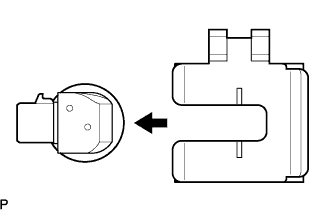
| 1. INSTALL NO. 1 ULTRASONIC SENSOR |
Install the No. 1 ultrasonic sensor to the rear bumper.
Install the sensor retainer as shown in the illustration.
Connect the sensor connector.
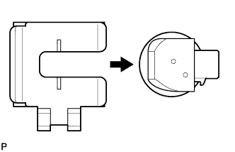
| 2. INSTALL NO. 2 ULTRASONIC SENSOR |
Install the No. 2 ultrasonic sensor to the rear bumper.
Install the sensor retainer as shown in the illustration.
Connect the sensor connector.
| 3. INSTALL REAR BUMPER ASSEMBLY (for 4GR-FSE) |
| 4. INSTALL REAR BUMPER ASSEMBLY (for 2AD-FHV) |
| 5. INSTALL REAR BUMPER PLATE |
| 6. CONNECT LUGGAGE ROOM WIRE |
| 7. INSTALL SIDE LUGGAGE COMPARTMENT TRIM COVER |
| 8. INSTALL LUGGAGE COMPARTMENT TRIM HOOK |
| 9. INSTALL FRONT LUGGAGE COMPARTMENT TRIM COVER |
| 11. INSTALL ROOM LIGHT ASSEMBLY |
| 12. INSTALL ROPE HOOK ASSEMBLY |
| 13. INSTALL REAR LUGGAGE COMPARTMENT TRIM COVER |
| 14. INSTALL SPARE WHEEL COVER |
| 15. INSTALL DECK SIDE TRIM BOX RH |
| 16. INSTALL DECK SIDE TRIM BOX LH |
| 17. INSTALL LUGGAGE COMPARTMENT TRIM COVER |
| 18. INSTALL NO. 1 ULTRASONIC SENSOR |
Install the No. 1 ultrasonic sensor to the front bumper.
Install the sensor retainer as shown in the illustration.
Connect the sensor connector.
| 19. INSTALL FRONT BUMPER ASSEMBLY |
| 20. INSTALL COOL AIR INTAKE DUCT SEAL |
| 21. VEHICLE PREPARATION FOR FOG LIGHT AIM |
Prepare the vehicle:
- Ensure there is no damage or deformation to the body around the fog lights.
- Fill the fuel tank.
- Make sure that the oil is filled to the specified level.
- Make sure that the coolant is filled to the specified level.
- Inflate the tires to the appropriate pressure.
- Place the spare tire, tools, and jack in their original positions.
- Unload the trunk.
- Sit a person of average weight (75 kg, 165 lb) in the driver's seat.
| 22. PREPARATION FOR FOG LIGHT AIMING |
Prepare the vehicle according to the following conditions:
- Place the vehicle in a location that is dark enough to clearly observe the cutoff line. The cutoff line is a distinct line, below which light from the fog lights can be observed and above which it cannot.
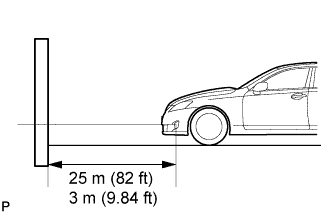
- Place the vehicle at a 90° angle to the wall.
- Create a 25m (82 ft) distance between the vehicle (fog light bulb center) and the wall.
- Place the vehicle on a level surface.
- Bounce the vehicle up and down to settle the suspension.
- NOTICE:
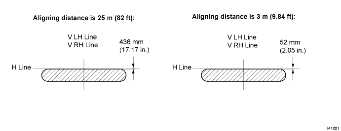
- A distance of 25 m (82 ft) between the vehicle (fog light bulb center) and the wall is necessary for proper aim adjustment. If unavailable, secure a distance of exactly 3 m (9.84 ft) for check and adjustment. (The target zone will change with the distance, so follow the instructions in the illustration.)
Prepare a piece of thick white paper (approximately 2 m (6.6 ft) (height) x 4 m (13.1 ft) (width)) to use as a screen.
Draw a vertical line down the center of screen (V line).
Set the screen as shown in the illustration.
- HINT:
- Stand the screen perpendicular to the ground.
- Align the V line on the screen with the center of the vehicle.
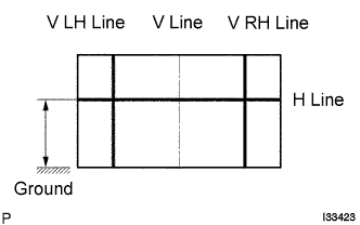
Draw base lines (H line, V LH, V RH lines) on the screen as shown in the illustration.
- HINT:
- Mark the fog light bulb center marks on the screen. If the center mark cannot be observed on the fog light, use the center of the fog light bulb or the manufacturer's name marked on the fog light as the center mark.
H Line (Fog light height):
Draw a horizontal line across the screen so that it passes through the center marks. The H line should be at the same height as the fog light bulb center marks of the low-beam fog lights.
V LH Line, V RH Line (Center mark position of left-hand (LH) and right-hand (RH) fog lights):
Draw two vertical lines so that they intersect the H line at each center mark.
| 23. FOG LIGHT AIMING INSPECTION |
Cover the fog light or disconnect the connector of the fog light on the opposite side to prevent light from the fog light not being inspected from affecting fog light aiming inspection.
Start the engine.
Turn on the fog light and make sure that the cutoff line falls within the specified area, as shown in the illustration.
| 24. FOG LIGHT AIMING ADJUSTMENT |
Adjust the fog light aim into the specified range by turning the aiming screw with a screwdriver.
- NOTICE:
- The final turn of the aiming screw should be made in the clockwise direction. If the screw is tightened excessively, loosen it and then retighten it, so that the final turn of the screw is in the clockwise direction.