Engine Immobiliser System (For 2Ad-Fhv) Certification Ecu Power Source Circuit
DESCRIPTION
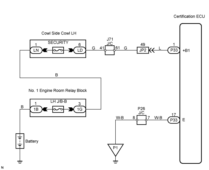
WIRING DIAGRAM
INSPECTION PROCEDURE
INSPECT FUSE (SECURITY)
CHECK HARNESS AND CONNECTOR (CERTIFICATION ECU - BATTERY)
CHECK HARNESS AND CONNECTOR (CERTIFICATION ECU - BODY GROUND)
ENGINE IMMOBILISER SYSTEM (for 2AD-FHV) - Certification ECU Power Source Circuit |
DESCRIPTION
This circuit provides power to operate the certification ECU.
WIRING DIAGRAM
INSPECTION PROCEDURE
| 1.INSPECT FUSE (SECURITY) |
Remove the SECURITY fuse from the cowl side junction block RH.
Measure the resistance of the fuse.
- Standard resistance:
- Below 1 Ω
| 2.CHECK HARNESS AND CONNECTOR (CERTIFICATION ECU - BATTERY) |
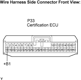
Disconnect the P33 ECU connector.
Measure the voltage according to the value(s) in the table below.
- Standard voltage:
Tester Connection
| Condition
| Specified Condition
|
P33-1 (+B1) - Body ground
| Always
| 10 to 14 V
|
| | REPAIR OR REPLACE HARNESS OR CONNECTOR |
|
|
| 3.CHECK HARNESS AND CONNECTOR (CERTIFICATION ECU - BODY GROUND) |
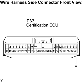
Measure the resistance according to the value(s) in the table below.
- Standard resistance:
Tester Connection
| Condition
| Specified Condition
|
P33-17 (E) - Body ground
| Always
| Below 1 Ω
|
| | REPAIR OR REPLACE HARNESS OR CONNECTOR |
|
|
| OK |
|
|
|
| PROCEED TO NEXT CIRCUIT INSPECTION SHOWN IN PROBLEM SYMPTOMS TABLE |
|