Theft Deterrent System (W/O Intrusion Sensor) Engine Hood Courtesy Switch Circuit
DESCRIPTION
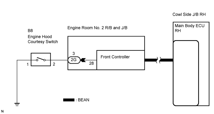
WIRING DIAGRAM
INSPECTION PROCEDURE
INSPECT DTC
READ VALUE OF INTELLIGENT TESTER
INSPECT ENGINE HOOD COURTESY SWITCH
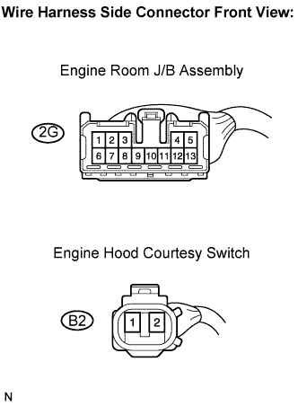
CHECK HARNESS AND CONNECTOR (ENGINE ROOM R/B NO. 2 - ENGINE HOOD COURTESY SWITCH)
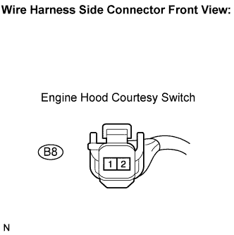
CHECK HARNESS AND CONNECTOR (ENGINE HOOD COURTESY SWITCH - BODY GROUND)
THEFT DETERRENT SYSTEM (w/o Intrusion Sensor) - Engine Hood Courtesy Switch Circuit |
DESCRIPTION
The engine hood courtesy switch is installed together with the hood lock. This switch turns on when the engine hood is opened and turns off when the engine hood is closed.
WIRING DIAGRAM
INSPECTION PROCEDURE
- HINT:
- Front controller sends engine hood open/close signal to main body ECU RH through the multiplex communication.
Delete DTC (Click here).
Check the DTC B1214.
- OK:
- No DTC is output.
| | GO TO MULTIPLEX COMMUNICATION SYSTEM |
|
|
| 2.READ VALUE OF INTELLIGENT TESTER |
Connect the intelligent tester to the DLC3.
Turn the engine switch on (IG).
Turn the intelligent tester main switch on.
Select the item below in the Data list and read the display on the tester.
Body No. 5 (Front controller):Item
| Test Details
| Diagnostic Note
|
Hood Courtesy Switch
| Engine hood courtesy switch signal ON/OFF
| -
|
- OK:
- The indicator on the tester switches between ON and OFF in accordance with the engine hood courtesy switch status.
| OK |
|
|
|
| REPLACE ENGINE ROOM NO. 2 RELAY BLOCK AND JUNCTION BLOCK (FRONT CONTROLLER) |
|
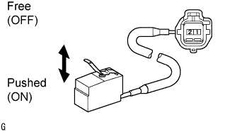
| 3.INSPECT ENGINE HOOD COURTESY SWITCH |
Remove the courtesy switch from the hood lock.
Disconnect the 2G R/B connector.
Measure the resistance according to the value(s) in the table below.
- Standard resistance:
Tester Connection
| Switch Position
| Specified Condition
|
1 - 2
| Free (OFF)
| 10 kΩ or higher
|
Pushed (ON)
| Below 1 Ω
|
| | REPLACE HOOD LOCK ASSEMBLY |
|
|
| 4.CHECK HARNESS AND CONNECTOR (ENGINE ROOM R/B NO. 2 - ENGINE HOOD COURTESY SWITCH) |
Disconnect the 2G R/B connector and B8 switch connector.
Measure the resistance according to the value(s) in the table below.
- Standard resistance:
Tester Connection
| Specified Condition
|
2G-3 - B8-2
| Below 1 Ω
|
2G-3 or B8-2 - Body ground
| 10 kΩ or higher
|
| | REPAIR OR REPLACE HARNESS OR CONNECTOR |
|
|
| 5.CHECK HARNESS AND CONNECTOR (ENGINE HOOD COURTESY SWITCH - BODY GROUND) |
Measure the resistance according to the value(s) in the table below.
- Standard resistance:
Tester Connection
| Specified Condition
|
B8-1 - Body ground
| Below 1 Ω
|
| | REPAIR OR REPLACE HARNESS OR CONNECTOR |
|
|
| OK |
|
|
|
| PROCEED TO NEXT CIRCUIT INSPECTION SHOWN IN PROBLEM SYMPTOMS TABLE |
|