Steering Gear Installation
Steering. Lexus Is250, Is220D. Gse20 Ale20
INSTALL POWER STEERING GEAR ASSEMBLY
CONNECT TIE ROD END LH
CONNECT TIE ROD END RH
INSTALL STEERING SLIDING YOKE SUB-ASSEMBLY (for Except 2AD-FHV RHD)
CONNECT NO. 2 STEERING INTERMEDIATE SHAFT ASSEMBLY (for 2AD-FHV RHD)
INSTALL FRONT LOWER SUSPENSION MEMBER PROTECTOR
INSTALL NO. 2 ENGINE UNDER COVER
INSTALL ENGINE UNDER COVER
INSTALL FRONT WHEELS
CONNECT CABLE TO NEGATIVE BATTERY TERMINAL
PLACE FRONT WHEELS FACING STRAIGHT AHEAD
INSPECT AND ADJUST FRONT WHEEL ALIGNMENT
PERFORM INITIALIZATION
INITIALIZE ROTATION ANGLE SENSOR AND CALIBRATE TORQUE SENSOR ZERO POINT
Steering Gear -- Installation |
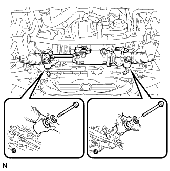
| 1. INSTALL POWER STEERING GEAR ASSEMBLY |
Install the power steering gear assembly with the 2 bolts, 2 washers, and 2 nuts.
- Torque:
- 118 N*m{1,200 kgf*cm, 87 ft.*lbf}
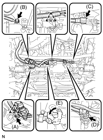
Install the power steering earth wire to the power steering gear assembly with bolt (B).
- Torque:
- 5.0 N*m{51 kgf*cm, 44 in.*lbf}
Connect wire harness connector (E) to the power steering gear assembly and securely lock the connector.
Connect 2 wire harness connectors (C) and (D) to the power steering gear assembly.
Install the 2 wire harness clamps to the power steering gear assembly.
Connect the earth wire to the bracket with bolt (A).
- Torque:
- 8.0 N*m{82 kgf*cm, 71 in.*lbf}
| 2. CONNECT TIE ROD END LH |
Connect the tie rod end LH to the steering knuckle with the nut.
- Torque:
- 65 N*m{663 kgf*cm, 50 ft.*lbf}
Install a new clip.
- NOTICE:
- If the holes for the clip are not aligned, tighten the nut up to 60° further.
| 3. CONNECT TIE ROD END RH |
- HINT:
- Perform the same procedure as for the LH side.
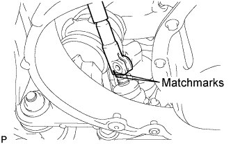
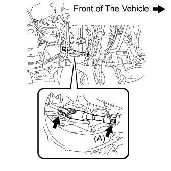
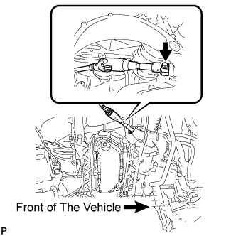
| 4. INSTALL STEERING SLIDING YOKE SUB-ASSEMBLY (for Except 2AD-FHV RHD) |
Align the matchmarks on the steering sliding yoke sub-assembly and the power steering gear assembly.
Install bolt (A) and tighten the 2 bolts.
- Torque:
- 35 N*m{360 kgf*cm, 26 ft.*lbf}
| 5. CONNECT NO. 2 STEERING INTERMEDIATE SHAFT ASSEMBLY (for 2AD-FHV RHD) |
Align the matchmarks on the No. 2 steering intermediate shaft assembly and the power steering gear assembly.
Install the bolt.
- Torque:
- 35 N*m{360 kgf*cm, 26 ft.*lbf}
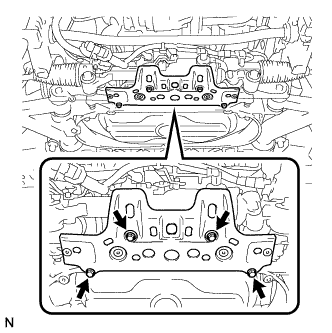
| 6. INSTALL FRONT LOWER SUSPENSION MEMBER PROTECTOR |
Install the front lower suspension member protector to the front suspension cross member with the 4 bolts.
- Torque:
- 8.0 N*m{82 kgf*cm, 71 in.*lbf}
| 7. INSTALL NO. 2 ENGINE UNDER COVER |
| 8. INSTALL ENGINE UNDER COVER |
- Torque:
- 103 N*m{1,050 kgf*cm, 76 ft.*lbf}
| 10. CONNECT CABLE TO NEGATIVE BATTERY TERMINAL |
| 11. PLACE FRONT WHEELS FACING STRAIGHT AHEAD |
| 12. INSPECT AND ADJUST FRONT WHEEL ALIGNMENT |
- HINT:
- Click here
| 13. PERFORM INITIALIZATION |
- HINT:
- Some systems need initialization when disconnecting the cable from the negative battery terminal (Click here).
| 14. INITIALIZE ROTATION ANGLE SENSOR AND CALIBRATE TORQUE SENSOR ZERO POINT |
- HINT:
- Click here