Land Cruiser URJ200 URJ202 GRJ200 VDJ200 - 3UR-FE LUBRICATION
ENGINE OIL COOLER - INSTALLATION
| 1. INSTALL OIL COOLER SPACER |
Apply a light coat of engine oil to a new gasket.
Install the gasket to the oil cooler spacer.
Install the oil cooler spacer to the oil filter bracket with the bolt.
- Torque:
- 10 N*m{ 102 kgf*cm, 7 ft.*lbf}
| 2. INSTALL OIL COOLER ASSEMBLY |
Apply a light coat of engine oil to 2 new O-rings.
Install the 2 O-rings to the oil cooler.
Install the oil cooler with the 5 nuts.
- Torque:
- 21 N*m{ 214 kgf*cm, 15 ft.*lbf}
| 3. INSTALL OIL FILTER BRACKET |
Apply a light coat of engine oil to 2 new O-rings.
Install the 2 O-rings to the timing chain cover.
Install the oil filter bracket with the 2 nuts and 2 bolts.
- Torque:
- 35 N*m{ 357 kgf*cm, 26 ft.*lbf}
| 4. INSTALL NO. 1 OIL COOLER BRACKET |
Connect the ground wire to the cylinder block.
Install the oil cooler bracket with the 2 nuts.
- Torque:
- 21 N*m{ 214 kgf*cm, 15 ft.*lbf}
| 5. INSTALL NO. 2 WATER BY-PASS PIPE SUB-ASSEMBLY |
Connect the 4 hoses.
Install the water by-pass hose with the 3 bolts.
- Torque:
- 10 N*m{ 102 kgf*cm, 7 ft.*lbf}
| 6. CONNECT COOLER COMPRESSOR ASSEMBLY |

Install the cooler compressor with the stud bolt.
- Torque:
- 10 N*m{ 102 kgf*cm, 7 ft.*lbf}
Install the 3 bolts and nut.
- Torque:
- 25 N*m{ 250 kgf*cm, 18 ft.*lbf}
- NOTICE:
- Tighten the bolts and nut in the order shown in the illustration to install the cooler compressor.
| 7. INSTALL OIL PRESSURE SENDER GAUGE ASSEMBLY |
Apply adhesive to 2 or 3 threads of the oil pressure sender gauge.
- Adhesive:
- Toyota Genuine Adhesive 1344, Three Bond 1344 or equivalent
- NOTICE:

- Do not allow adhesive to contact the oil hole.
| *1 | Oil Hole |
Install the oil pressure sender gauge.
- Torque:
- 15 N*m{ 153 kgf*cm, 11 ft.*lbf}
- NOTICE:
- Do not start the engine within 1 hour after installation.
Connect the sender gauge connector.
| 8. INSTALL OIL FILTER ELEMENT |
Clean the inside of the oil filter cap, its threads and its O-ring groove.
Apply a small amount of engine oil to a new O-ring and install it to the oil filter cap.
Set a new oil filter element to the oil filter cap.
Remove any dirt or foreign matter from the installation surface of the engine.
Apply a small amount of engine oil to the O-ring again and temporarily install the oil filter cap.
- NOTICE:
- Do not remove the oil filter bracket clip.
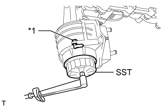
Using SST, tighten the oil filter cap.
- SST
- 09228-06501
- Torque:
- 25 N*m{ 255 kgf*cm, 18 ft.*lbf}
| *1 | Oil Filter Bracket Clip |
- NOTICE:

Apply a small amount of engine oil to a new drain plug O-ring, and install it to the oil filter cap.
| *1 | O-Ring |
- NOTICE:
- Before installing the O-ring, remove any dirt or foreign matter from the installation surface of the oil filter cap.
Install the oil filter drain plug.
- Torque:
- 13 N*m{ 127 kgf*cm, 9 ft.*lbf}
- NOTICE:
- Be careful that the O-ring does not get caught between any surrounding parts.
Install the No. 2 engine under cover seal with the 2 bolts.
- Torque:
- 10 N*m{ 102 kgf*cm, 7 ft.*lbf}
| 9. INSTALL FAN AND GENERATOR V BELT |
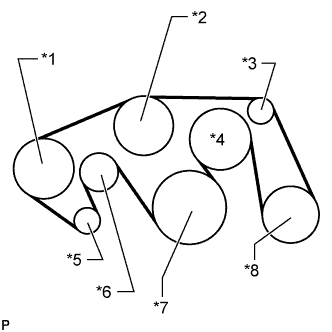
Set the V belt onto every part.
While turning the belt tensioner counterclockwise, remove the bar.
| *1 | Vane Pump |
| *2 | Water Pump |
| *3 | No. 1 Idler |
| *4 | Fan |
| *5 | Generator |
| *6 | Belt Tensioner |
| *7 | Crankshaft |
| *8 | Cooler Compressor |
- NOTICE:
- Make sure that the V belt is properly set to each pulley.
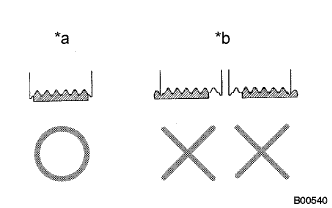
After installing the belt, check that it fits properly in the ribbed grooves.
| *a | CORRECT |
| *b | INCORRECT |
- HINT:
- Make sure to check by hand that the belt has not slipped out of the grooves on the bottom of the pulley.
| 10. INSTALL V-BANK COVER SUB-ASSEMBLY |
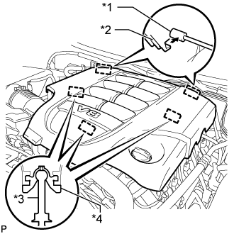
Attach the 2 V-bank cover hooks to the bracket. Then align the 3 V-bank cover grommets with the 3 pins, and press down on the V-bank cover to attach the pins.
| *1 | Bracket |
| *2 | Hook |
| *3 | Pin |
| *4 | Grommet |
| 11. ADD ENGINE OIL |
Add fresh oil and install the oil filler cap.
- Standard Oil Grade:
Oil Grade Oil Viscosity (SAE) API grade SL "Energy-Conserving", SM "Energy-Conserving", SN "Resource-Conserving" or ILSAC multigrade engine oil 5W-30
10W-30API grade SL, SM or SN multigrade engine oil 15W-40
20W-50
- Standard Oil Capacity:
Item Specified Condition Drain and refill without oil filter change 7.1 liters (7.5 US qts, 6.2 Imp. qts) Drain and refill with oil filter change 7.5 liters (7.9 US qts, 6.6 Imp. qts) Dry fill 9.3 liters (9.8 US qts, 8.2 Imp. qts)
| 12. ADD ENGINE COOLANT |
Add engine coolant.
- Standard Capacity:
Item Specified Condition with rear heater 16.2 liters (17.1 US qts, 14.3 Imp. qts) without rear heater 13.4 liters (14.2 US qts, 11.8 Imp. qts)
- NOTICE:
- Do not substitute plain water for engine coolant.
- HINT:
- TOYOTA vehicles are filled with TOYOTA SLLC at the factory. In order to avoid damage to the engine cooling system and other technical problems, only use TOYOTA SLLC or similar high quality ethylene glycol based non-silicate, non-amine, non-nitrite, non-borate coolant with long-life hybrid organic acid technology (coolant with long-life hybrid organic acid technology consists of a combination of low phosphates and organic acids).
Slowly pour coolant into the radiator reservoir until it reaches the F line.
Install the reservoir cap.
Press the No. 1 and No. 2 radiator hoses several times by hand, and then check the coolant level. If the coolant level is low, add coolant.
Install the radiator cap.
Start the engine and warm it up until the thermostat opens.
- HINT:
- The thermostat opening timing can be confirmed by pressing the radiator inlet hose by hand, and checking when the engine coolant starts to flow inside the hose.
Maintain the engine speed at 2000 to 2500 rpm.
- NOTICE:
Press the No. 1 and No. 2 radiator hoses several times by hand to bleed air.
- CAUTION:
Stop the engine, and wait until the engine coolant cools down to ambient temperature.
- CAUTION:
- Do not remove the radiator cap while the engine and radiator are still hot. Pressurized, hot engine coolant and steam may be released and cause serious burns.
Check that the coolant level is between the F and L lines.
If the coolant level is below the L line, repeat all of the procedures above.
If the coolant level is above the F line, drain coolant so that the coolant level is between the F and L lines.
| 13. INSPECT FOR OIL LEAK |
Start the engine. Make sure that there are no oil leaks from the area that was worked on.
| 14. INSPECT ENGINE OIL LEVEL |
Warm up the engine. Then stop the engine and wait for 5 minutes.
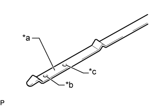
Check that the engine oil level is between the dipstick low level mark and full level mark.
| *a | Measuring Surface |
| *b | Low Level Mark |
| *c | Full Level Mark |
If the level is low, check for leakage and add oil up to the full level mark.
- NOTICE:
- Do not fill engine oil above the full level mark.
- HINT:
- A certain amount of engine oil will be consumed while driving. In the following situations, oil consumption may increase, and engine oil may need to be refilled in between oil maintenance intervals.
- When judging the amount of oil consumption, keep in mind that the oil may have become diluted, making it difficult to judge the true level accurately.
| 15. INSPECT FOR COOLANT LEAK |
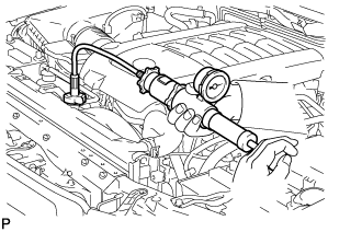
- CAUTION:
- Do not remove the radiator cap while the engine and radiator are still hot. Pressurized, hot engine coolant and steam may be released and cause serious burns.
Fill the radiator with coolant and attach a radiator cap tester.
Warm up the engine.
Using the radiator cap tester, increase the pressure inside the radiator to 123 kPa (1.3 kgf/cm2, 18 psi), and check that the pressure does not drop.
If the pressure drops, check the hoses, radiator and water pump for leaks. If no external leaks are found, check the heater core, cylinder block and head.
| 16. INSTALL NO. 1 ENGINE UNDER COVER SUB-ASSEMBLY |
Install the No. 1 engine under cover with the 10 bolts.
- Torque:
- 29 N*m{ 296 kgf*cm, 21 ft.*lbf}
| 17. INSTALL FRONT FENDER SPLASH SHIELD SUB-ASSEMBLY LH |
Push in the clip to install the front fender splash shield sub-assembly LH.
Install the 3 bolts and screw.
| 18. INSTALL FRONT FENDER SPLASH SHIELD SUB-ASSEMBLY RH |
Push in the clip to install the front fender splash shield sub-assembly RH.
Install the 3 bolts and 2 screws.