Front Speed Sensor Installation
Brake. Lexus Is250, Is220D. Gse20 Ale20
INSTALL FRONT SPEED SENSOR
INSTALL FRONT AXLE HUB SUB-ASSEMBLY
INSPECT FRONT AXLE HUB BEARING FOR LOOSENESS
INSPECT FRONT AXLE HUB FOR RUNOUT
INSTALL FRONT DISC
INSTALL FRONT DISC BRAKE CALIPER ASSEMBLY
CONNECT FRONT SPEED SENSOR
INSTALL FRONT WHEEL
INSPECT SPEED SENSOR SIGNAL
Front Speed Sensor -- Installation |
| 1. INSTALL FRONT SPEED SENSOR |
Wipe off sealant attached to the front speed sensor's fitting surface with white gasoline.
- NOTICE:
- Prevent foreign matter from attaching to the sensor rotor.
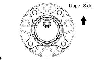
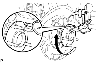
Install a new front speed sensor to the hub and bearing assembly. The front speed sensor connector should be placed in the upper position.
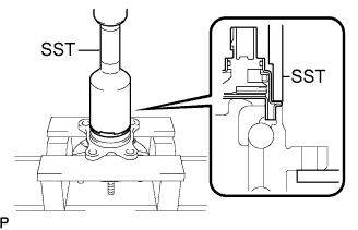
Using the SST and press, install the skid control sensor onto the hub and bearing.
- SST
- 09214-76011
- NOTICE:
- Keep the sensor away from magnets.
- Do not use a hammer on the front speed sensor.
- Check that there is no foreign matter such as iron chips on the front speed sensor's detecting portion.
- Slowly press the front speed sensor straight.
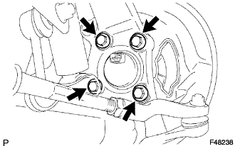
| 2. INSTALL FRONT AXLE HUB SUB-ASSEMBLY |
Install the front axle hub sub-assembly and front disc brake dust cover with the 4 bolts.
- Torque:
- 69 N*m{702 kgf*cm, 51 ft.*lbf}
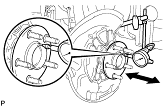
| 3. INSPECT FRONT AXLE HUB BEARING FOR LOOSENESS |
Using a dial indicator, check for looseness near the center of the axle hub.
- Maximum:
- 0.05 mm (0.0020 in.)
- NOTICE:
- Ensure that the dial indicator is perpendicular to the measurement surface.
If looseness exceeds the maximum, replace the front axle hub.
| 4. INSPECT FRONT AXLE HUB FOR RUNOUT |
Using a dial indicator, check for runout on the surface of the axle hub outside the hub bolt.
- Maximum:
- 0.05 mm (0.0020 in.)
- NOTICE:
- Ensure that the dial indicator is set perpendicular to the measurement surface.
If runout exceeds the maximum, replace the front axle hub.
Align the matchmarks and install the front disc.
- HINT:
- When replacing the disc with a new one, select the installation position where the front disc has the minimum runout.
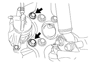
| 6. INSTALL FRONT DISC BRAKE CALIPER ASSEMBLY |
Install the brake caliper assembly and new No. 1 caliper plates to the steering knuckle with the 2 bolts.
- Torque:
- 78 N*m{795 kgf*cm, 58 ft.*lbf}
- NOTICE:
- Do not twist the front brake hose when installing the front disc brake caliper.
- Make sure that there are no foreign objects or damage to the threads of the bolts.
- Do not overtighten the bolts because the steering knuckle is made of aluminum and may be damaged easily.
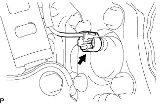
| 7. CONNECT FRONT SPEED SENSOR |
Connect the speed sensor connector to the front speed sensor.
- NOTICE:
- Do not twist the sensor wire.
- Torque:
- 103 N*m{1,050 kgf*cm, 76 ft.*lbf}
| 9. INSPECT SPEED SENSOR SIGNAL |
- HINT:
- without VDIM (Click here)
- with VDIM (Click here)