Dtc C1231/31 Steering Angle Sensor Circuit Malfunction
Brake. Lexus Is250, Is220D. Gse20 Ale20
DESCRIPTION
WIRING DIAGRAM
INSPECTION PROCEDURE
CHECK DTC
INSPECT STEERING ANGLE SENSOR (POWER SOURCE TERMINAL)
INSPECT STEERING ANGLE SENSOR (GROUND TERMINAL)
DTC C1231/31 Steering Angle Sensor Circuit Malfunction |
DESCRIPTION
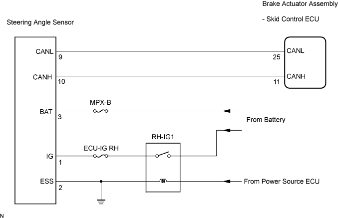
The steering angle sensor signal is sent to the skid control ECU via CAN communication system. When there is a malfunction in the CAN communication system, it will be detected by the steering angle sensor zero point malfunction diagnostic function.DTC No.
| DTC Detection Condition
| Trouble Area
|
C1231/31
| When ECU IG1 terminal voltage is 9.5 V or more, the steering angle sensor malfunction signal is received.
| - Steering angle sensor
- Steering angle sensor circuit
- Steering angle sensor power supply
- Brake actuator assembly (Skid control ECU)
|
WIRING DIAGRAM
INSPECTION PROCEDURE
- HINT:
- When U0073/94, U0123/62, U0124/95 or U0126/63 is output together with C1231/31, inspect and repair the trouble areas indicated by U0073/94, U0123/62, U0124/95 or U0126/63 first.
- When the speed sensor or the yaw rate sensor has trouble, DTCs for the steering angle sensor may be output even when the steering angle sensor is normal. When DTCs for the speed sensor or yaw rate sensor are output together with other DTCs for the steering angle sensor, inspect and repair the speed sensor and yaw rate sensor first, and then inspect and repair the steering angle sensor.
Clear the DTC (Click here).
Turn the engine switch off.
Turn the engine switch on (IG) again and check that no CAN communication system DTC is output.
Drive the vehicle and turn the steering wheel to the right and left at the speed of 22 mph (35 km/h) and check that no speed sensor and yaw rate sensor DTCs are output.
- Result:
Condition
| Proceed to
|
No CAN communication system DTC and the speed sensor or yaw rate sensor DTC are output
| A
|
CAN communication system DTC is output
| B
|
Speed sensor or yaw rate sensor DTC is output
| C (Click here)
|
- HINT:
- If there is a malfunction in the speed sensor or the yaw rate sensor, an abnormal value may be output although the steering angle sensor is normal.
- If the speed sensor and the yaw rate sensor DTCs are output simultaneously, repair the sensors and inspect the steering angle sensor.
| | INSPECT CAN COMMUNICATION SYSTEM |
|
|
| | REPAIR CIRCUIT INDICATED BY OUTPUT DTC |
|
|
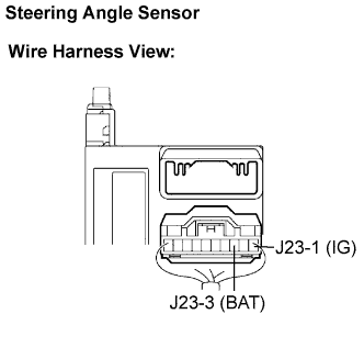
| 2.INSPECT STEERING ANGLE SENSOR (POWER SOURCE TERMINAL) |
Turn the engine switch off.
Remove the steering wheel and the column cover lower.
Disconnect the steering angle sensor connector.
Measure the voltage according to the value(s) in the table below.
- Standard voltage:
Tester Connection
| Condition
| Specified Condition
|
J23-1 (IG) - Body ground
| Engine switch on (IG)
| 10 to 14 V
|
J23-3 (BAT) - Body ground
| Always
| 10 to 14 V
|
| | REPAIR OR REPLACE HARNESS OR CONNECTOR (POWER SOURCE CIRCUIT) |
|
|
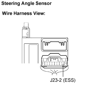
| 3.INSPECT STEERING ANGLE SENSOR (GROUND TERMINAL) |
Turn the engine switch off.
Measure the resistance according to the value(s) in the table below.
- Standard resistance:
Tester Connection
| Condition
| Specified Condition
|
J23-2 (ESS) - Body ground
| Always
| Below 1 Ω
|
- HINT:
- If troubleshooting has been carried out according to the Problem Symptoms Table, refer back to the table and proceed to the next step (Click here).
| | REPAIR OR REPLACE HARNESS OR CONNECTOR (GROUND CIRCUIT) |
|
|
| OK |
|
|
|
| REPLACE STEERING ANGLE SENSOR |
|