Can Communication System Skid Control Ecu With Actuator Communication Stop Mode
DESCRIPTION
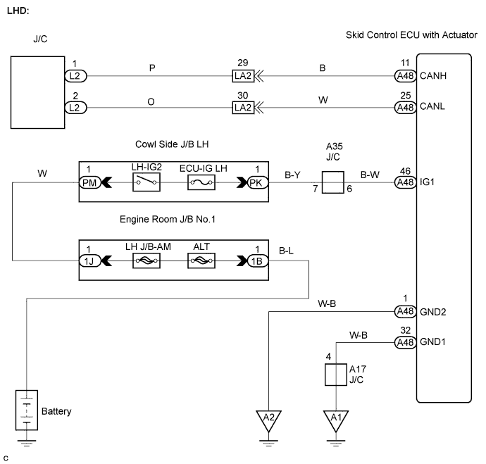
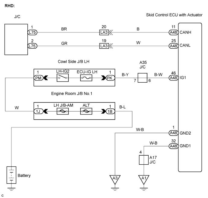
WIRING DIAGRAM
INSPECTION PROCEDURE
CHECK CAN BUS LINE CONNECTION (SKID CONTROL ECU WITH ACTUATOR SUB BUS LINE)
CHECK WIRE HARNESS (IG1, GND1, GND2)
CAN COMMUNICATION SYSTEM - Skid Control ECU with Actuator Communication Stop Mode |
DESCRIPTION
Detection Item
| Symptom
| Trouble Area
|
SKID CONTROL ECU WITH ACTUATOR COMMUNICATION STOP MODE
| - ABS/VSC/TRC is not displayed on the "COMMUNICATION BUS CHECK" screen of the intelligent tester
- Applies to SKID CONTROL ECU WITH ACTUATOR COMMUNICATION STOP MODE" in the "DTC COMBINATION TABLE"
| - Power source or inside the skid control ECU with actuator
- Skid control ECU with actuator sub bus line or connector
|
WIRING DIAGRAM
INSPECTION PROCEDURE
| 1.CHECK CAN BUS LINE CONNECTION (SKID CONTROL ECU WITH ACTUATOR SUB BUS LINE) |
Turn the engine switch off.
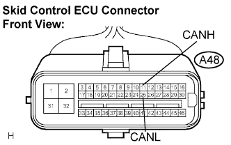
Disconnect the skid control ECU with actuator connector (A48).
Measure the resistance according to the value(s) in the table below.
- Standard resistance:
Tester connection
| Condition
| Specified Value
|
A48-11 (CANH) - A48-25 (CANL)
| Engine switch off
| 54 to 69 Ω
|
| | REPAIR OR REPLACE SKID CONTROL ECU SUB BUS LINE OR CONNECTOR (CAN-H, CAN-L) |
|
|
| 2.CHECK WIRE HARNESS (IG1, GND1, GND2) |
Measure the resistance according to the value(s) in the table below.
- Standard resistance:
Tester Connection
| Condition
| Specified Value
|
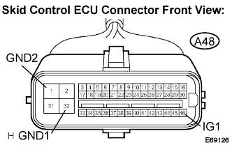
A48-1 (GND2) - Body ground
| Always
| Below 1 Ω
|
A48-32 (GND1) - Body ground
| Always
| Below 1 Ω
|
Measure the voltage according to the value(s) in the table below.
- Standard voltage:
Tester Connection
| Condition
| Specified Value
|
A48-46 (IG1) - Body ground
| Engine switch on (IG)
| 10 to 14 V
|
| | REPAIR OR REPLACE HARNESS OR CONNECTOR |
|
|
| OK |
|
|
|
| REPLACE SKID CONTROL ECU WITH ACTUATOR |
|