Dtc B1262 A/C Ecu Communication Stop
DESCRIPTION
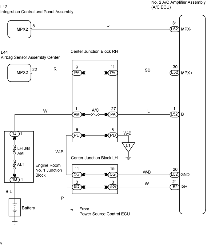
WIRING DIAGRAM
INSPECTION PROCEDURE
CHECK OPERATION
CHECK WIRE HARNESS (No. 2 AIR CONDITIONING AMPLIFIER ASSEMBLY (A/C ECU) - BATTERY AND BODY GROUND)
CHECK RESISTANCE OF COMMUNICATION LINE
DTC B1262 A/C ECU Communication Stop |
DESCRIPTION
- This DTC is detected when communication between the No. 2 A/C control amplifier (A/C ECU) and gateway ECU stops for more than 10 seconds.
DTC No.
| DTC Detection Condition
| Trouble Area
|
B1262
| A/C ECU communication stops
| - No. 2 A/C control amplifier assembly (A/C ECU)
- Wire harness
|
WIRING DIAGRAM
INSPECTION PROCEDURE
Check that the A/C switch can operate the A/C normally.
- OK:
- A/C switch can operate A/C normally.
| OK |
|
|
|
| REPLACE No. 2 AIR CONDITIONING AMPLIFIER ASSEMBLY (A/C ECU) |
|
| 2.CHECK WIRE HARNESS (No. 2 AIR CONDITIONING AMPLIFIER ASSEMBLY (A/C ECU) - BATTERY AND BODY GROUND) |
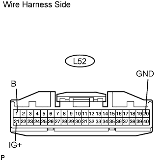
Disconnect the L52 ECU connector.
Measure the resistance and voltage of the wire harness side connector.
- Standard voltage:
Tester Connection
| Condition
| Specified Condition
|
L52-21 (IG+) - Body ground
| Engine switch on (IG)
| 10 to 14 V
|
L52-1 (B) - Body ground
| Always
| 10 to 14 V
|
- Standard resistance:
Tester Connection
| Condition
| Specified Condition
|
L52-20 (GND) - Body ground
| Always
| Below 1 Ω
|
| | REPAIR OR REPLACE HARNESS AND CONNECTOR |
|
|
| 3.CHECK RESISTANCE OF COMMUNICATION LINE |
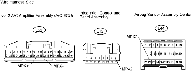
Disconnect the L52 ECU connector.
Disconnect the L12 panel connector.
Disconnect the L44 sensor connector.
Measure the resistance of the wire harness side connectors.
- Standard resistance:
Tester Connection
| Specified Condition
|
L52-30 (MPX+) - L44-22 (MPX2)
| Below 1 Ω
|
L52-31 (MPX-) - L12-8 (MPX2)
| Below 1 Ω
|
- Result:
Result
| Proceed to
|
Both are OK
| A
|
One is OK
| B
|
Both are NG
| C
|
| | REPLACE No. 2 AIR CONDITIONING AMPLIFIER ASSEMBLY AND HARNESS AND CONNECTOR |
|
|
| | REPAIR OR REPLACE HARNESS AND CONNECTOR |
|
|
| A |
|
|
|
| REPLACE No. 2 AIR CONDITIONING AMPLIFIER ASSEMBLY (A/C ECU) |
|