Dtc B1297 Clearance Sonar Ecu Communication Stop
DESCRIPTION
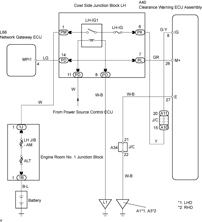
WIRING DIAGRAM
INSPECTION PROCEDURE
CHECK OPERATION
INSPECT FUSE (LH-IG)
CHECK WIRE HARNESS (CLEARANCE SONAR ECU - BODY GROUND)
CHECK RESISTANCE OF COMMUNICATION LINE
DTC B1297 Clearance Sonar ECU Communication Stop |
DESCRIPTION
DTC No.
| DTC Detection Condition
| Trouble Area
|
B1297
| Clearance warning ECU assembly communication stops
| - Clearance warning ECU assembly
- Wire harness
|
WIRING DIAGRAM
INSPECTION PROCEDURE
Turn the engine switch on (IG) and the clearance sonar main switch ON. Check that the combination meter displays the graphic of the system check operation for approximately 2 seconds as it checks for an open circuit and a malfunction in the sensor. Also, check that the buzzer emits a sound for approximately 1 second.
- OK:
- System check graphic is displayed on combination meter for approximately 2 seconds and buzzer sound is emitted for approximately 1 second.
| OK |
|
|
|
| REPLACE CLEARANCE SONAR ECU |
|
Remove the LH-HG fuse from the junction block.
Measure the resistance of the wire harness side connector.
- Standard resistance:
- Below 1 Ω
| 3.CHECK WIRE HARNESS (CLEARANCE SONAR ECU - BODY GROUND) |
Disconnect the A40 ECU connector.
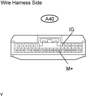
Measure the voltage and resistance of the wire harness side connector.
- Standard voltage:
Tester Connection
| Condition
| Specified Condition
|
A40-8 (IG) - Body ground
| Engine switch off→on (IG)
| 0 V → 10 to 14 V
|
- Standard resistance:
Tester Connection
| Condition
| Specified Condition
|
A40-26 (M+) - Body ground
| Constant
| Below 1 Ω
|
| | REPAIR OR REPLACE HARNESS AND CONNECTOR |
|
|
| 4.CHECK RESISTANCE OF COMMUNICATION LINE |
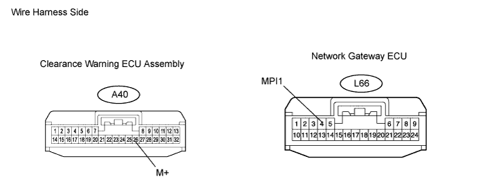
Disconnect the A40 ECU connector.
Disconnect the L66 ECU connector.
Measure the resistance between the wire harness side connectors.
- Standard resistance:
Tester Connection
| Specified Condition
|
A40-26 (M+) - L66-4 (MPI1)
| Below 1 Ω
|
| | REPAIR OR REPLACE HARNESS AND CONNECTOR |
|
|
| OK |
|
|
|
| REPLACE CLEARANCE SONAR ECU |
|