Dtc B1211 Driver Door Ecu Communication Stop
DESCRIPTION
WIRING DIAGRAM
INSPECTION PROCEDURE
CHECK OPERATION
CHECK WIRE HARNESS (MULTIPLEX NETWORK DOOR ECU FRONT LH (DOOR ECU LH) - BATTERY AND BODY GROUND)
CHECK RESISTANCE OF COMMUNICATION LINE
DTC B1211 Driver Door ECU Communication Stop |
DESCRIPTION
- This DTC is detected when communication between the multiplex network door ECU front LH (front door ECU LH) and the network gateway ECU stops for more than 10 seconds.
DTC No.
| DTC Detection Condition
| Trouble Area
|
B1211
| Multiplex network door ECU front LH communication stops
| - Multiplex network door ECU front LH (front door ECU LH)
- Wire harness
|
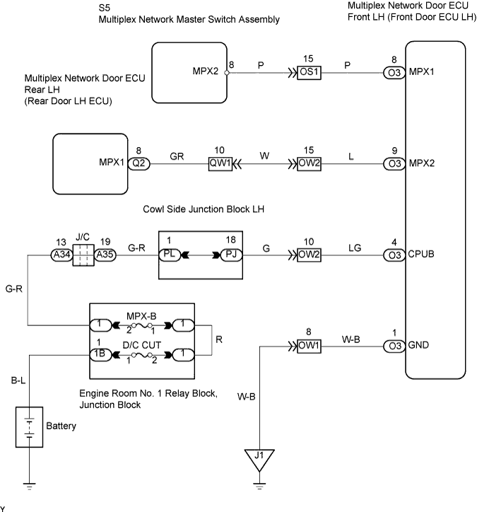
WIRING DIAGRAM
INSPECTION PROCEDURE
Open the driver door and check that the door warning light (built into the combination meter) illuminates.
- OK:
- Door warning light illuminates.
| OK |
|
|
|
| REPLACE MULTIPLEX NETWORK DOOR ECU FRONT LH (FRONT DOOR ECU LH) |
|
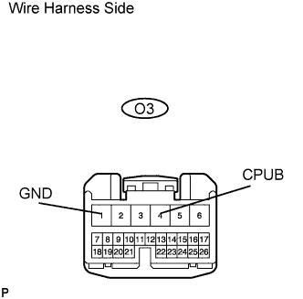
| 2.CHECK WIRE HARNESS (MULTIPLEX NETWORK DOOR ECU FRONT LH (DOOR ECU LH) - BATTERY AND BODY GROUND) |
Disconnect the O3 ECU connector.
Measure the voltage and resistance of the wire harness side connector.
- Standard voltage:
Tester Connection
| Specified Condition
|
O3-4 (CPUB) - Body ground
| 10 to 14 V
|
- Standard resistance:
Tester Connection
| Specified Condition
|
O3-1 (GND) - Body ground
| Below 1 Ω
|
| | REPAIR OR REPLACE HARNESS AND CONNECTOR |
|
|
| 3.CHECK RESISTANCE OF COMMUNICATION LINE |
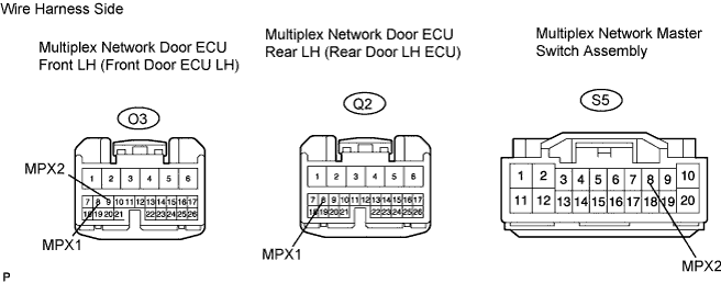
Disconnect the O3 and Q2 ECU connectors.
Disconnect the S5 switch connector.
Measure the resistance of the wire harness side connectors.
- Standard resistance:
Tester Connection
| Specified Condition
|
O3-8 (MPX1) - Q2-8 (MPX1)
| Below 1 Ω
|
O3-9 (MPX2) - S5-8 (MPX2)
| Below 1 Ω
|
- Result:
Result
| Proceed to
|
Both are OK
| A
|
One is OK
| B
|
Both are NG
| C
|
| | REPLACE MULTIPLEX NETWORK DOOR ECU FRONT LH AND HARNESS AND CONNECTOR |
|
|
| | REPAIR OR REPLACE HARNESS AND CONNECTOR |
|
|
| A |
|
|
|
| REPLACE MULTIPLEX NETWORK DOOR ECU FRONT LH (FRONT DOOR ECU LH) |
|