Dtc B1206 P/W Master Switch Communication Stop
DESCRIPTION
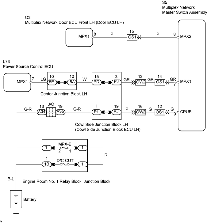
WIRING DIAGRAM
INSPECTION PROCEDURE
CHECK OPERATION
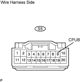
CHECK WIRE HARNESS (MULTIPLEX NETWORK MASTER SWITCH ASSEMBLY - BATTERY)
CHECK RESISTANCE OF COMMUNICATION
DTC B1206 P/W Master Switch Communication Stop |
DESCRIPTION
- This DTC is detected when communication between the multiplex network master switch and network gateway ECU stops for more than 10 seconds.
DTC No.
| DTC Detection Condition
| Trouble Area
|
B1206
| Multiplex network master switch communication stops
| - Multiplex network master switch assembly
- Wire harness
|
WIRING DIAGRAM
INSPECTION PROCEDURE
Turn the engine switch on (IG) and check that the power window can be operated using the multiplex network master switch.
- OK:
- Power window can be operated using multiplex network master switch.
| | REPLACE MULTIPLEX NETWORK MASTER SWITCH ASSEMBLY |
|
|
| 2.CHECK WIRE HARNESS (MULTIPLEX NETWORK MASTER SWITCH ASSEMBLY - BATTERY) |
Disconnect the S5 switch connector.
Measure the voltage of the wire harness side connector.
- Standard voltage:
Tester Connection
| Specified Connection
|
S5-9 (CPUB) - Body ground
| 10 to 14 V
|
| | REPAIR OR REPLACE HARNESS AND CONNECTOR |
|
|
| 3.CHECK RESISTANCE OF COMMUNICATION |
Disconnect the S5, O3 and L73 ECU connectors.
Measure the resistance of the wire harness side connectors.
- Standard resistance:
Tester Connection
| Specified Condition
|
S5-7 (MPX1) - L73-7 (MPX1)
| Below 1 Ω
|
S5-8 (MPX2) - O3-8 (MPX1)
| Below 1 Ω
|
- Result:
Result
| Proceed to
|
Both are OK
| A
|
One is OK
| B
|
Both are NG
| C
|
| | REPLACE MULTIPLEX MASTER SWITCH ASSEMBLY AND HARNESS AND CONNECTOR |
|
|
| | REPAIR OR REPLACE HARNESS AND CONNECTOR |
|
|
| A |
|
|
|
| REPLACE MULTIPLEX NETWORK MASTER SWITCH ASSEMBLY |
|