Dtc B1200 Mpx Body Ecu Stop
DESCRIPTION
WIRING DIAGRAM
INSPECTION PROCEDURE
INSPECT FUSE (MPX-B, D/C CUT)
CHECK WIRE HARNESS COWL SIDE JUNCTION BLOCK RH (MULTIPLEX NETWORK BODY ECU - BATTERY AND BODY GROUND)
CHECK RESISTANCE OF COMMUNICATION LINE
DTC B1200 MPX Body ECU Stop |
DESCRIPTION
- This DTC is detected when communication between the cowl side junction block RH (cowl side junction block ECU RH) and network gateway ECU stops for more than 10 seconds.
DTC No.
| DTC Detection Condition
| Trouble Area
|
B1200
| Body ECU communication stops
| - Cowl side junction block RH (cowl side junction block ECU RH)
- Wire harness
|
WIRING DIAGRAM
INSPECTION PROCEDURE
| 1.INSPECT FUSE (MPX-B, D/C CUT) |
Remove the MPX-B and D/C CUT fuses from the engine room No. 1 relay block.
Measure the resistance of the fuses.
- Standard resistance:
- Below 1 Ω
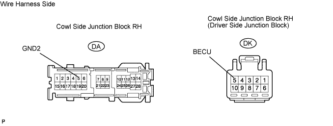
| 2.CHECK WIRE HARNESS COWL SIDE JUNCTION BLOCK RH (MULTIPLEX NETWORK BODY ECU - BATTERY AND BODY GROUND) |
Disconnect the DA and DK junction block connectors.
Measure the resistance and voltage of the wire harness side connectors.
- Standard voltage:
Tester Connection
| Specified Condition
|
DK-5 (BECU) - Body ground
| 10 to 14 V
|
- Standard resistance:
Tester Connection
| Specified Condition
|
DA-5 (GND2) - Body ground
| Below 1 Ω
|
| | REPAIR OR REPLACE HARNESS AND CONNECTOR |
|
|
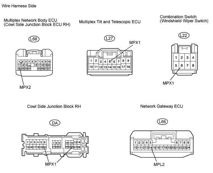
| 3.CHECK RESISTANCE OF COMMUNICATION LINE |
Disconnect the DA junction block connector.
Disconnect the L66, L68 and L27 ECU connectors.
Disconnect the L22 switch connector.
Measure the resistance of the wire harness side connectors.
- Standard resistance:
Tester Connection
| Specified Condition
|
DA-26 (MPX1) - L66-14 (MPL2)
| Below 1 Ω
|
DA-20 (MPX1) - L27-5 (MPX1)
| Below 1 Ω
|
L68-21 (MPX2) - L22-6 (MPX1)
| Below 1 Ω
|
- Result:
Result
| Proceed to
|
All are OK
| A
|
One or two is / are OK
| B
|
All are NG
| C
|
| | REPLACE COWL SIDE JUNCTION BLOCK RH (MULTIPLEX NETWORK BODY ECU) AND REPAIR OR REPLACE HARNESS AND CONNECTOR |
|
|
| | REPAIR OR REPLACE HARNESS AND CONNECTOR |
|
|
| A |
|
|
|
| REPLACE COWL SIDE JUNCTION BLOCK RH (MULTIPLEX NETWORK BODY ECU) |
|