Land Cruiser URJ200 URJ202 GRJ200 VDJ200 - 1VD-FTV INTAKE / EXHAUST
EXHAUST MANIFOLD W/ TURBOCHARGER - REMOVAL
- NOTICE:
- w/ DPF:
- When fuel lines are disconnected, air may enter the fuel lines, leading to engine starting trouble. Therefore, perform forced regeneration and bleed the air from the fuel lines,
| 1. PRECAUTION |
- NOTICE:
- After turning the ignition switch off, waiting time may be required before disconnecting the cable from the battery terminal. Therefore, make sure to read the disconnecting the cable from the battery terminal notice before proceeding with work ().
| 2. DISCONNECT CABLE FROM NEGATIVE BATTERY TERMINAL |
- NOTICE:
- When disconnecting the cable some systems need to be initialized after the cable is reconnected ().
| 3. REMOVE ENGINE ASSEMBLY |
()
| 4. REMOVE NO. 1 ENGINE OIL LEVEL DIPSTICK GUIDE (for Bank 1) |
Remove the 2 bolts and No. 1 engine oil level dipstick guide.
Remove the O-ring from the No. 1 engine oil level dipstick.
| 5. REMOVE NO. 1 INTAKE AIR CONNECTOR PIPE (for Bank 1) |
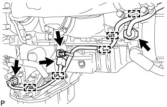
Disconnect the 4 connectors.
Using a clip remover, detach the 5 wire harness clamps.
Loosen the hose clamp, and remove the bolt and No. 1 intake air connector pipe.
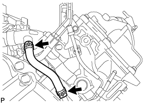
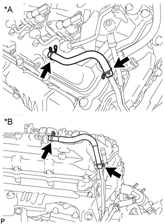
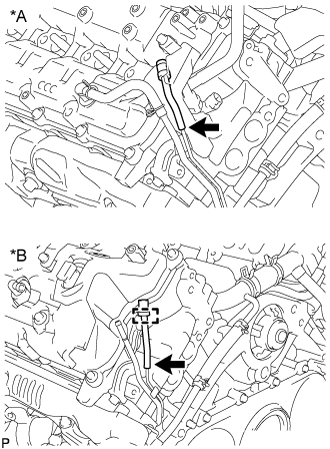
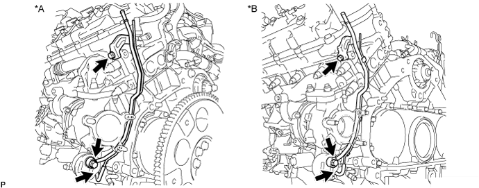
| 6. REMOVE NO. 2 VENTILATION HOSE (for Bank 1) |
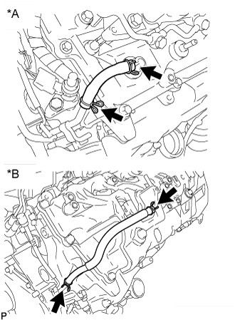
| *A | w/ DPF |
| *B | w/o DPF |
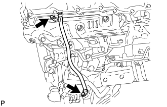
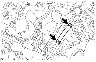
| 7. REMOVE NO. 2 TURBO WATER HOSE (for Bank 1) |
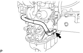
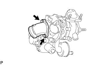
| 8. REMOVE BREATHER PLUG RH (for Bank 1) |

Disconnect the hose.
Detach the clamp and remove the breather plug RH.
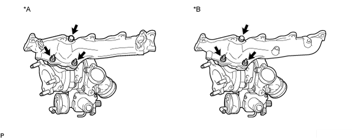
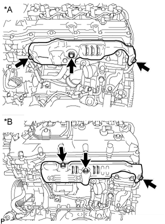
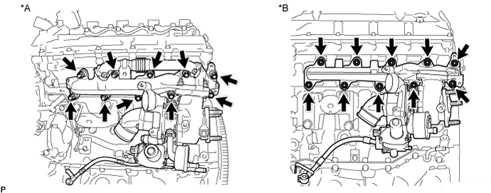
| 9. REMOVE NO. 1 EXHAUST MANIFOLD HEAT INSULATOR (for Bank 1) |
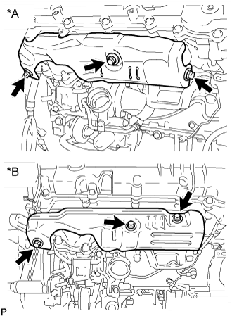
Remove the 3 bolts and No. 1 exhaust manifold heat insulator.
| *A | w/ DPF |
| *B | w/o DPF |
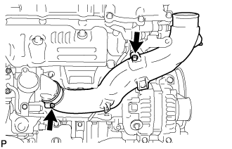
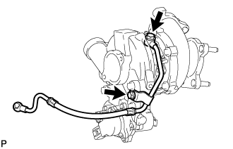
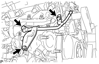
| 10. DISCONNECT NO. 1 OUTLET TURBO OIL HOSE (for Bank 1) |
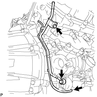
| 11. REMOVE NO. 1 TURBO WATER PIPE SUB-ASSEMBLY (for Bank 1) |

Disconnect the water hose.
Remove the 3 bolts, 2 nuts, No. 1 turbo water pipe and gasket.
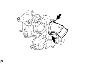
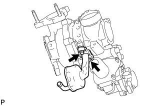
| 12. REMOVE NO. 1 TURBOCHARGER STAY (for Bank 1) |
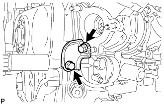
Remove the 2 bolts and No. 1 turbocharger stay.
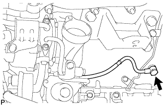
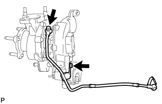
| 13. REMOVE NO. 1 VENTILATION TUBE SUB-ASSEMBLY (for Bank 1) |
Disconnect the hose.
Remove the union bolt, bolt, No. 1 ventilation tube and gasket.
| 14. REMOVE NO. 1 TURBOCHARGER SUB-ASSEMBLY WITH EXHAUST MANIFOLD RH (for Bank 1) |
Remove the union bolt and gasket, and disconnect the No. 1 inlet turbo oil pipe from the cylinder block.
Remove the 10 nuts, 10 collars and No. 1 turbocharger with exhaust manifold RH.
| *A | w/ DPF | *B | w/o DPF |
Remove the gasket.
w/ DPF:
Remove the 4 bolts, No. 1 exhaust manifold pipe and 2 gaskets.
Remove the 2 nuts and bolt, and separate the No. 1 turbocharger and exhaust manifold RH.
| *A | w/ DPF | *B | w/o DPF |
Remove the gasket from the No. 1 turbocharger.
| 15. REMOVE NO. 1 INLET COMPRESSOR ELBOW (for Bank 1) |
Remove the 2 bolts, No. 1 inlet compressor elbow and gasket.
| 16. REMOVE NO. 1 TURBO OIL PIPE (for Bank 1) |

Remove the 2 bolts, No. 1 turbo oil pipe and gasket.
| 17. REMOVE NO. 1 INLET TURBO OIL PIPE SUB-ASSEMBLY (for Bank 1) |
Remove the union bolt, bolt, No. 1 inlet turbo oil pipe and gasket.
| 18. REMOVE NO. 3 VENTILATION HOSE (for Bank 2) |
| *A | w/ DPF |
| *B | w/o DPF |
| 19. REMOVE BREATHER PLUG LH (for Bank 2) |
Disconnect the hose.
| *A | w/ DPF |
| *B | w/o DPF |
w/o DPF:
Detach the clamp.
Remove the breather plug LH.
| 20. REMOVE NO. 2 TURBO WATER HOSE (for Bank 2) |
| 21. REMOVE NO. 2 EXHAUST MANIFOLD HEAT INSULATOR (for Bank 2) |
Remove the 3 bolts and No. 2 exhaust manifold heat insulator.
| *A | w/ DPF |
| *B | w/o DPF |
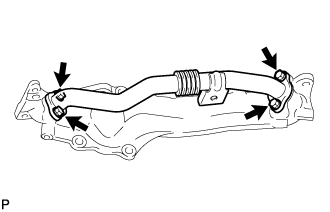
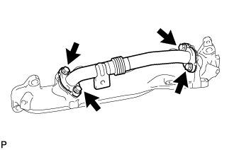
| 22. REMOVE NO. 3 TURBO WATER PIPE SUB-ASSEMBLY (for Bank 2) |
Remove the 2 bolts, union bolt, No. 3 turbo water pipe and gasket.
| 23. REMOVE FRONT WATER BY-PASS JOINT (for Bank 2) |

Remove the front water by-pass joint and gasket.
| 24. REMOVE NO. 2 TURBO WATER PIPE SUB-ASSEMBLY (for Bank 2) |

Disconnect the water hose.
Remove the union bolt, bolt, No. 2 turbo water pipe and gasket.
| 25. REMOVE NO. 2 OUTLET TURBO OIL HOSE (for Bank 2) |

| 26. REMOVE NO. 2 TURBOCHARGER STAY (for Bank 2) |

Remove the 2 bolts and No. 2 turbocharger stay.
| 27. REMOVE NO. 2 VENTILATION TUBE SUB-ASSEMBLY (for Bank 2) |
Disconnect the hose.
| *A | w/ DPF | *B | w/o DPF |
Remove the union bolt, bolt, No. 2 ventilation tube and gasket.
| 28. REMOVE NO. 2 TURBOCHARGER SUB-ASSEMBLY WITH EXHAUST MANIFOLD LH (for Bank 2) |

Disconnect the 2 connectors from the turbocharger.

Remove the union bolt and gasket, and disconnect the No. 2 inlet turbo oil pipe from the No. 1 oil pan.
Remove the 10 nuts, 10 collars and No. 2 turbocharger with exhaust manifold LH.
| *A | w/ DPF | *B | w/o DPF |
Remove the gasket.
w/ DPF:
Remove the 4 bolts, No. 2 exhaust manifold pipe and 2 gaskets.
Remove the 3 nuts, and separate the No. 2 turbocharger and exhaust manifold LH.
| *A | w/ DPF |
| *B | w/o DPF |
Remove the gasket from the turbocharger.
| 29. REMOVE NO. 2 INLET COMPRESSOR ELBOW (for Bank 2) |
Remove the 2 bolts, No. 2 inlet compressor elbow and gasket.
| 30. REMOVE NO. 2 TURBO OIL PIPE (for Bank 2) |
Remove the 2 bolts, No. 2 turbo oil pipe and gasket.
| 31. REMOVE NO. 2 INLET TURBO OIL PIPE SUB-ASSEMBLY (for Bank 2) |
Remove the union bolt, bolt, No. 2 inlet turbo oil pipe and gasket.
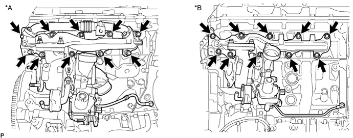
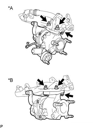
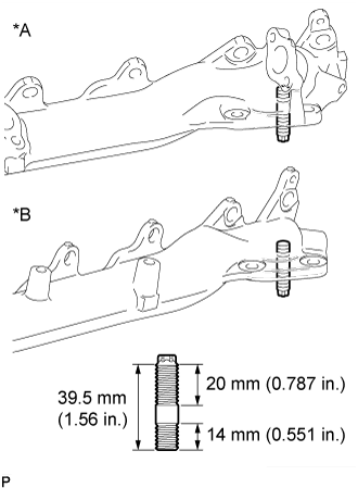
| 32. REPLACE STUD BOLT |
- HINT:
- If a stud bolt is deformed or its threads are damaged, replace it.
For No. 1 Turbocharger:
Using an E10 "TORX" wrench, replace the stud bolts labeled A and B shown in the illustration below.
- Torque:
- 20 N*m{ 204 kgf*cm, 15 ft.*lbf}
Replace the stud bolts labeled C shown in the illustration below.
- Torque:
- 6.0 N*m{ 61 kgf*cm, 53 in.*lbf}


For No. 2 Turbocharger:
Using an E10 "TORX" wrench, replace the stud bolt.
- Torque:
- 20 N*m{ 204 kgf*cm, 15 ft.*lbf}
For Exhaust Manifold LH:
| *A | w/ DPF |
| *B | w/o DPF |
Using an E10 "TORX" wrench, replace the stud bolt.
- Torque:
- 20 N*m{ 204 kgf*cm, 15 ft.*lbf}