Navigation System Microphone Circuit Between Overhead J/B And Multi-Display
DESCRIPTION
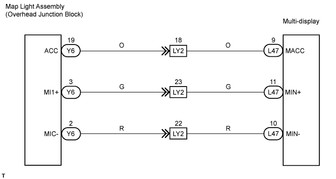
WIRING DIAGRAM
INSPECTION PROCEDURE
CHECK MULTI-DISPLAY
CHECK WIRE HARNESS (MAP LIGHT ASSEMBLY - MULTI-DISPLAY)
REPLACE MAP LIGHT ASSEMBLY
NAVIGATION SYSTEM - Microphone Circuit between Overhead J/B and Multi-display |
DESCRIPTION
This circuit sends a microphone signal from the multi-display to the map light assembly.
WIRING DIAGRAM
INSPECTION PROCEDURE
Measure the voltage of the connector.
- Standard voltage:
Tester Connection
| Condition
| Specified Condition
|
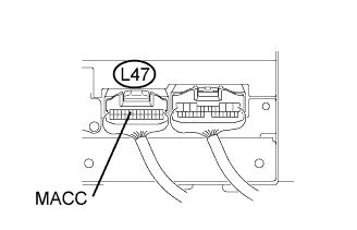
L47-9 (MACC) - Body ground
| Engine switch on (ACC)
| 4 to 6 V
|
| 2.CHECK WIRE HARNESS (MAP LIGHT ASSEMBLY - MULTI-DISPLAY) |
Disconnect the Y6 light connector.
Disconnect the L47 multi-display connector.
Measure the resistance of the wire harness side connectors.
- Standard resistance:
Tester Connection
| Condition
| Specified Condition
|
Y6-19 (ACC) - L47-9 (MACC)
| Always
| Below 1 Ω
|
Y6-3 (MI1+) - L47-11 (MIN+)
| Always
| Below 1 Ω
|
Y6-2 (MIC-) - L47-10 (MIN-)
| Always
| Below 1 Ω
|
Y6-19 (ACC) - Body ground
| Always
| 10 kΩ or higher
|
Y6-3 (MI1+) - Body ground
| Always
| 10 kΩ or higher
|
Y6-2 (MIC-) - Body ground
| Always
| 10 kΩ or higher
|
| | REPAIR OR REPLACE HARNESS AND CONNECTOR |
|
|
| 3.REPLACE MAP LIGHT ASSEMBLY |
Replace the map light assembly with a normal one and check if the same problem occurs again.
- OK:
- Same problem does not occur.
| OK |
|
|
|
| PROCEED TO NEXT CIRCUIT INSPECTION SHOWN IN DIAGNOSTIC TROUBLE CODE CHART |
|