Navigation System Avc-Lan Circuit Between Radio Receiver And Gateway Ecu
DESCRIPTION
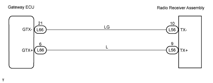
WIRING DIAGRAM
INSPECTION PROCEDURE
INSPECT RADIO RECEIVER ASSEMBLY
CHECK WIRE HARNESS (RADIO RECEIVER ASSEMBLY - GATEWAY ECU)
NAVIGATION SYSTEM - AVC-LAN Circuit between Radio Receiver and Gateway ECU |
DESCRIPTION
Each unit of the navigation system connected to the AVC-LAN (communication bus) communicates by transferring the signals from each switch.When +B and GND shorts occur in this AVC-LAN, the navigation system will not function normally as communication is discontinued.In the AVC-LAN, the multi-display becomes the communication master, and the radio receiver assembly has enough resistance necessary for transmitting the communication.
WIRING DIAGRAM
INSPECTION PROCEDURE
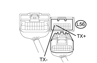
| 1.INSPECT RADIO RECEIVER ASSEMBLY |
Disconnect the L56 receiver connector.
Measure the resistance of the receiver.
- Standard resistance:
Tester Connection
| Condition
| Specified Condition
|
L56-9 (TX+) - L56-10 (TX-)
| Always
| 60 to 80 Ω
|
| | REPLACE RADIO RECEIVER ASSEMBLY |
|
|
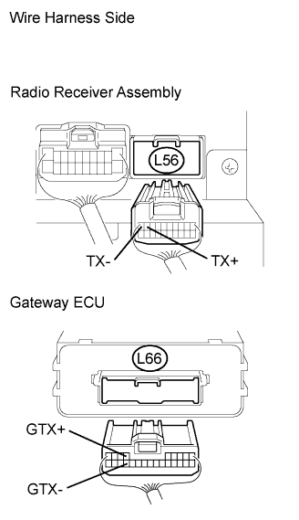
| 2.CHECK WIRE HARNESS (RADIO RECEIVER ASSEMBLY - GATEWAY ECU) |
Disconnect the L56 receiver connector.
Disconnect the L66 ECU connector.
Measure the resistance of the wire harness side connectors.
- Standard resistance:
Tester connection
| Condition
| Specified Condition
|
L56-9 (TX+) - L66-6 (GTX+)
| Always
| Below 1 Ω
|
L56-10 (TX-) - L66-21 (GTX-)
| Always
| Below 1 Ω
|
L56-9 (TX+) - Body ground
| Always
| 10 kΩ or higher
|
L56-10 (TX-) - Body ground
| Always
| 10 kΩ or higher
|
| | REPAIR OR REPLACE HARNESS AND CONNECTOR |
|
|
| OK |
|
|
|
| PROCEED TO NEXT CIRCUIT INSPECTION SHOWN IN DIAGNOSTIC TROUBLE CODE CHART |
|