Audio And Visual System Mute Signal Circuit Between Radio Receiver And Stereo Component Amplifier
DESCRIPTION
WIRING DIAGRAM
INSPECTION PROCEDURE
CHECK STEREO COMPONENT AMPLIFIER ASSEMBLY
CHECK WIRE HARNESS (RADIO RECEIVER ASSEMBLY - STEREO COMPONENT AMPLIFIER)
AUDIO AND VISUAL SYSTEM - Mute Signal Circuit between Radio Receiver and Stereo Component Amplifier |
DESCRIPTION
Mute signals are sent to the stereo component amplifier to mute noises that occur when changing the sound source. The mute signal also mutes CD audio, etc., when the navigation system's voice guidance is on. If the circuit is open: 1) noise will occur when the sound source is changed; and 2) if the navigation system is available, CD audio, etc., will not mute while the voice guidance is on. If the circuit is shorted, even if the amplifier is functioning properly, no sounds or only barely audible sounds will be output.
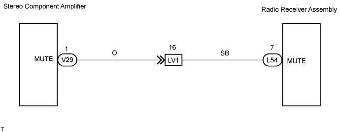
WIRING DIAGRAM
INSPECTION PROCEDURE
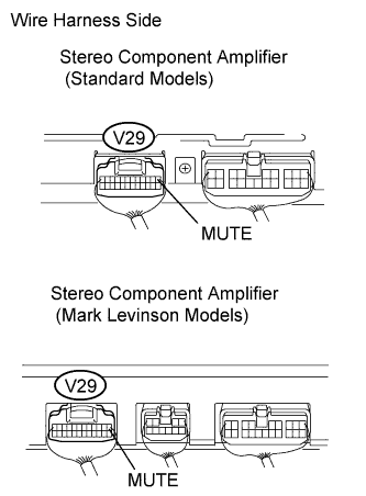
| 1.CHECK STEREO COMPONENT AMPLIFIER ASSEMBLY |
Measure the voltage of the connectors.
- Standard value:
Tester Connection
| Condition
| Specified Condition
|
V29-1 (MUTE) - Body ground
| Turn engine switch on (ACC)
Audio system is playing
| Above 3.5 V
|
Turn engine switch on (ACC)
Changing mode
| Below 1 V
|
| OK |
|
|
|
| PROCEED TO NEXT CIRCUIT INSPECTION SHOWN IN PROBLEM SYMPTOMS TABLE |
|
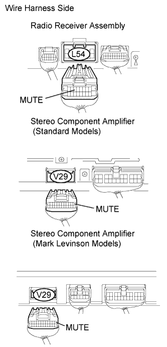
| 2.CHECK WIRE HARNESS (RADIO RECEIVER ASSEMBLY - STEREO COMPONENT AMPLIFIER) |
Disconnect the L54 radio receiver assembly and V29 stereo component amplifier connectors.
Measure the resistance of the wire harness side connectors.
- Standard resistance:
Tester Connection
| Condition
| Specified Condition
|
L54-7 (MUTE) - V29-1 (MUTE)
| Always
| Below 1 Ω
|
L54-7 (MUTE) - Body ground
| Always
| 10 kΩ or higher
|
V29-1 (MUTE) - Body ground
| Always
| 10 kΩ or higher
|
| | REPAIR OR REPLACE HARNESS AND CONNECTOR |
|
|
| OK |
|
|
|
| REPLACE RADIO RECEIVER ASSEMBLY |
|