Entry And Start System Entry Lock And Unlock Functions Do Not Operate On Front Passenger Side Door
DESCRIPTION
WIRING DIAGRAM
INSPECTION PROCEDURE
CHECK MANUAL DOOR LOCK AND UNLOCK OPERATION
PERFORM ACTIVE TEST (DOOR ELECTRICAL KEY OSCILLATOR FRONT RH)
CHECK WIRE HARNESS (CERTIFICATION ECU ASSEMBLY - DOOR ELECTRICAL KEY OSCILLATOR FRONT)
CHECK WIRE HARNESS (DOOR ELECTRICAL KEY OSCILLATOR FRONT - DOOR ELECTRICAL KEY ANTENNA FRONT)
CHECK WIRE HARNESS (DOOR ELECTRICAL KEY OSCILLATOR FRONT - MULTIPLEX NETWORK DOOR ECU FRONT)
CHECK WIRE HARNESS (DOOR ELECTRICAL KEY ANTENNA FRONT - MULTIPLEX NETWORK DOOR ECU FRONT)
CHECK OPERATION OF ELECTRICAL KEY ANTENNA FRONT
CHECK OPERATION OF DOOR ELECTRICAL KEY OSCILLATOR FRONT
ENTRY AND START SYSTEM - Entry Lock and Unlock Functions do not Operate on Front Passenger Side Door |
DESCRIPTION
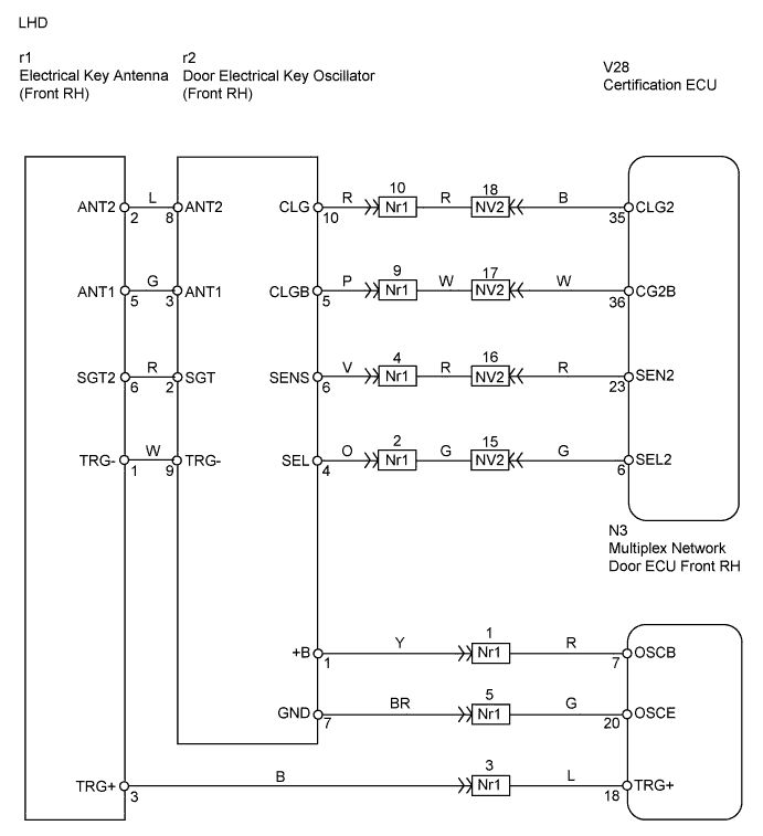
- LHD:
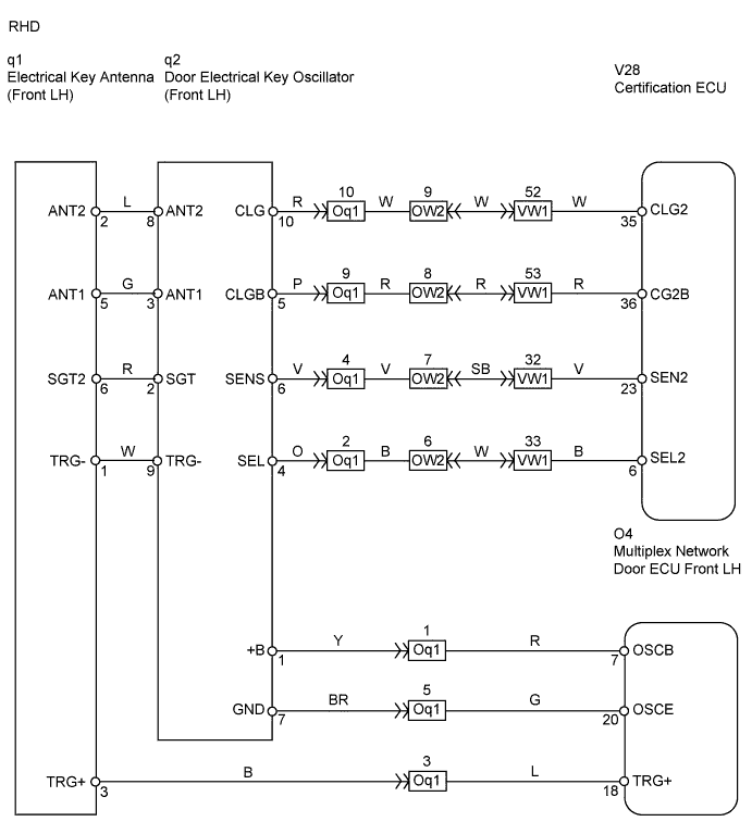
Both the entry lock and unlock functions do not operate when: 1) nothing is output from the door electrical key oscillator front RH, 2) the entry and start system is disabled through customization, or 3) the entire power door lock control system is malfunctioning.- RHD:
Both the entry lock and unlock functions do not operate when: 1) nothing is output from the door electrical key oscillator front LH, 2) the entry and start system is disabled through customization, or 3) the entire power door lock control system is malfunctioning.
WIRING DIAGRAM
INSPECTION PROCEDURE
| 1.CHECK MANUAL DOOR LOCK AND UNLOCK OPERATION |
Check that the manual door lock and unlock function operates normally.
- OK:
- Manual door lock and unlock function operates normally.
| | GO TO POWER DOOR LOCK CONTROL SYSTEM |
|
|
| 2.PERFORM ACTIVE TEST (DOOR ELECTRICAL KEY OSCILLATOR FRONT RH) |
Select the Active Test, use the intelligent tester to generate a control command, and then check that the oscillator operates.
Certification ECU:Item
| Test Details
| Diagnostic Note
|
P Transmitter
| Front passenger side transmitter ON / OFF
| -
|
- OK:
- When key is brought close to door oscillator that is OFF, indicator light on key illuminates.
| | REPLACE CERTIFICATION ECU ASSEMBLY |
|
|
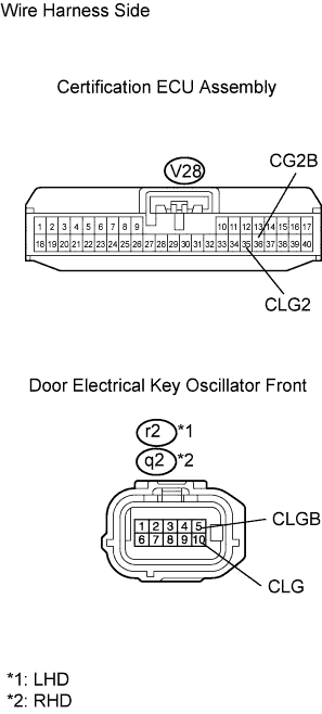
| 3.CHECK WIRE HARNESS (CERTIFICATION ECU ASSEMBLY - DOOR ELECTRICAL KEY OSCILLATOR FRONT) |
Disconnect the V28 ECU connector.
Disconnect the r2*1 or q2*2 oscillator connector.
Measure the resistance of the wire harness side connectors.
- Standard resistance:
Tester Connection
| Specified Condition
|
V28-35 (CLG2) - r2-10 (CLG)*1
V28-35 (CLG2) - q2-10 (CLG)*2
| Below 1 Ω
|
V28-36 (CG2B) - r2-5 (CLGB)*1
V28-36 (CG2B) - q2-5 (CLGB)*2
| Below 1 Ω
|
| | REPAIR OR REPLACE HARNESS AND CONNECTOR |
|
|
| 4.CHECK WIRE HARNESS (DOOR ELECTRICAL KEY OSCILLATOR FRONT - DOOR ELECTRICAL KEY ANTENNA FRONT) |
Disconnect the r2*1 or q2*2 oscillator connector.
Disconnect the r1*1 or q1*2 antenna connector.
Measure the resistance of the wire harness side connectors.
- Standard resistance:
Tester Connection
| Specified Condition
|
r2-2 (SGT) - r1-6 (SGT2)*1
q2-2 (SGT) - q1-6 (SGT2)*2
| Below 1 Ω
|
r2-3 (ANT1) - r1-5 (ANT1)*1
q2-3 (ANT1) - q1-5 (ANT1)*2
| Below 1 Ω
|
r2-8 (ANT2) - r1-2 (ANT2)*1
q2-8 (ANT2) - q1-2 (ANT2)*2
| Below 1 Ω
|
r2-9 (TRG-) - r1-1 (TRG-)*1
q2-9 (TRG-) - q1-1 (TRG-)*2
| Below 1 Ω
|
| | REPAIR OR REPLACE HARNESS AND CONNECTOR |
|
|
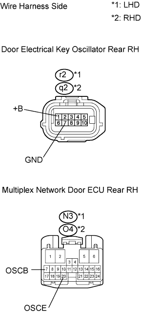
| 5.CHECK WIRE HARNESS (DOOR ELECTRICAL KEY OSCILLATOR FRONT - MULTIPLEX NETWORK DOOR ECU FRONT) |
Disconnect the r2*1 or q2*2 oscillator connector.
Disconnect the N3*1 or O4*2 ECU connector.
Measure the resistance of the wire harness side connectors.
- Standard resistance:
Tester Connection
| Specified Condition
|
r2-1 (+B) - N3-7 (OSCB)*1
q2-1 (+B) - O4-7 (OSCB)*2
| Below 1 Ω
|
r2-7 (GND) - N3-20 (OSCE)*1
q2-7 (GND) - O4-20 (OSCE)*2
| Below 1 Ω
|
| | REPAIR OR REPLACE HARNESS AND CONNECTOR |
|
|
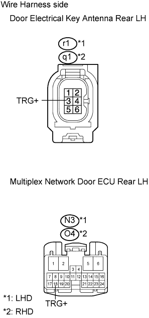
| 6.CHECK WIRE HARNESS (DOOR ELECTRICAL KEY ANTENNA FRONT - MULTIPLEX NETWORK DOOR ECU FRONT) |
Disconnect the r1*1 or q1*2 antenna connector.
Disconnect the N3*1 or O4*2 ECU connector.
Measure the resistance of the wire harness side connectors.
- Standard resistance:
Tester Connection
| Specified Condition
|
r1-3 (TRG+) - N3-18 (TRG+)*1
q1-3 (TRG+) - O4-18 (TRG+)*2
| Below 1 Ω
|
| | REPAIR OR REPLACE HARNESS AND CONNECTOR |
|
|
| 7.CHECK OPERATION OF ELECTRICAL KEY ANTENNA FRONT |
After replacing the electrical key antenna front with a normal one, check that the entry lock and unlock functions operate normally.
- OK:
- Entry lock and unlock functions operate normally.
| | END (ELECTRICAL KEY ANTENNA FRONT IS DEFECTIVE) |
|
|
| 8.CHECK OPERATION OF DOOR ELECTRICAL KEY OSCILLATOR FRONT |
After replacing the door electrical key oscillator front with a normal one, check that the entry lock and unlock functions operate normally.
- OK:
- Entry lock and unlock functions operate normally.
| | REPLACE CERTIFICATION ECU ASSEMBLY |
|
|
| OK |
|
|
|
| END (DOOR ELECTRICAL KEY OSCILLATOR FRONT IS DEFECTIVE) |
|