Entry And Start System Entry Unlock Function Does Not Operate On Driver Side Door
DESCRIPTION
WIRING DIAGRAM
INSPECTION PROCEDURE
CHECK MANUAL DOOR UNLOCK OPERATION
READ DATA LIST (DOOR COURTESY LIGHT SWITCH)
READ DATA LIST (LOCK POSITION SWITCH)
PERFORM ACTIVE TEST (DRIVER SIDE SELECT)
READ DATA LIST (D TOUCH SENSOR)
CHECK OPERATION OF MULTIPLEX NETWORK MASTER SWITCH ASSEMBLY
CHECK DOOR ELECTRICAL KEY OSCILLATOR FRONT
CHECK WIRE HARNESS (DOOR ELECTRICAL KEY OSCILLATOR FRONT - DOOR ELECTRICAL KEY ANTENNA FRONT)
CHECK WIRE HARNESS (ECU - OSCILLATOR)
ENTRY AND START SYSTEM - Entry Unlock Function does not Operate on Driver Side Door |
DESCRIPTION
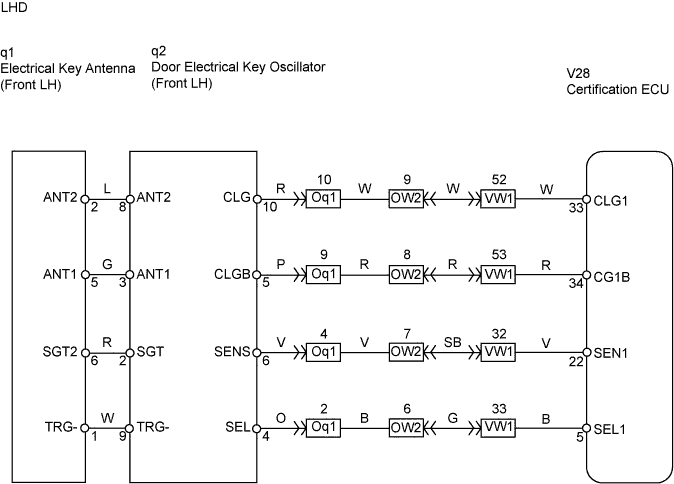
- LHD:
When an ID code from the door electrical key oscillator front LH matches an ID code from the key, the multiplex network door ECU front LH (driver door ECU) outputs a SEL signal (Lo when output) to the door electrical key oscillator front LH, activates the touch sensor inside the outside door handle, and enters unlock standby mode. When the touch sensor is touched, the door electrical key oscillator front LH sends a SENS signal (Lo when output) to the multiplex network door ECU front LH (driver door ECU) and the multiplex network door ECU front LH (drive door ECU) sends an unlock signal to the driver side door lock.- RHD:
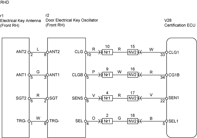
When an ID code from the door electrical key oscillator front RH matches an ID code from the key, the multiplex network door ECU front RH (driver door ECU) outputs a SEL signal (Lo when output) to the door electrical key oscillator front RH, activates the touch sensor inside the outside door handle, and enters unlock standby mode. When the touch sensor is touched, the door electrical key oscillator front RH sends a SENS signal (Lo when output) to the multiplex network door ECU front RH (driver door ECU) and the multiplex network door ECU front RH (drive door ECU) sends an unlock signal to the driver side door lock.
WIRING DIAGRAM
INSPECTION PROCEDURE
| 1.CHECK MANUAL DOOR UNLOCK OPERATION |
Check that the manual door unlock function operates normally.
- OK:
- Manual door unlock function operates normally.
| | GO TO POWER DOOR LOCK CONTROL SYSTEM |
|
|
| 2.READ DATA LIST (DOOR COURTESY LIGHT SWITCH) |
Check the Data List for proper functioning of the driver side door courtesy light switch.
Multiplex network master switch assembly:Item
| Measurement Item / Range (Display)
| Normal Condition
| Diagnostic Note
|
Courtesy SW
| Courtesy light switch / ON or OFF
| ON: Courtesy light switch is pushed
OFF: Courtesy light switch is not pushed
| -
|
- OK:
- ON (door courtesy light switch is pushed) appears on the screen.
| 3.READ DATA LIST (LOCK POSITION SWITCH) |
Check the Data List for proper functioning of the door lock position switch.
Multiplex network master switch assembly:Item
| Measurement Item / Range (Display)
| Normal Condition
| Diagnostic Note
|
Lock Pos SW
| Door unlock detection switch signal/ ON or OFF
| ON: Door is unlocked
OFF: Door is locked
| -
|
- OK:
- ON (Door is unlocked) appears on the screen.
| | GO TO POWER DOOR LOCK CONTROL SYSTEM |
|
|
| 4.PERFORM ACTIVE TEST (DRIVER SIDE SELECT) |
Select the Active Test, use the intelligent tester to generate a control command, and then check that the oscillator operates.
Certification ECU:Item
| Test Details
| Diagnostic Note
|
D Select Sig
| Driver side select / ON or OFF
| -
|
- OK:
- ON (D Select Sig is ON) appears on the screen.
| | REPLACE CERTIFICATION ECU ASSEMBLY |
|
|
| 5.READ DATA LIST (D TOUCH SENSOR) |
With "D Select Sig" ON, check the Data List for proper functioning of the touch sensor.
Certification ECU:Item
| Measurement Item / Range (Display)
| Normal Condition
| Diagnostic Note
|
D Touch Sensor
| Driver side door touch sensor / ON or OFF
| ON: Sensor is touched
OFF: Sensor is not touched
| -
|
- OK:
- When driver side is set to ON, ON (Sensor is touched) appears on the screen.
| 6.CHECK OPERATION OF MULTIPLEX NETWORK MASTER SWITCH ASSEMBLY |
After replacing the multiplex network master switch assembly with a normal one, check that the entry unlock function operates normally.
- OK:
- Entry unlock function operates normally.
| | REPLACE CERTIFICATION ECU ASSEMBLY |
|
|
| OK |
|
|
|
| END (MULTIPLEX NETWORK MASTER SWITCH ASSEMBLY IS DEFECTIVE) |
|
| 7.CHECK DOOR ELECTRICAL KEY OSCILLATOR FRONT |
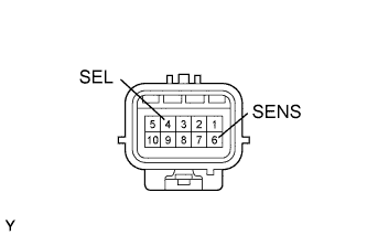
Measure the voltage of the oscillator connector.
- Standard voltage:
Tester Connection
| Condition
| Specified Condition
|
4 (SEL) - Body ground
| During Active Test
| Below 1 V
|
6 (SENS) - Body ground
| Touch sensor is touched during Active Test
| Below 1 V
|
| | REPLACE CERTIFICATION ECU ASSEMBLY |
|
|
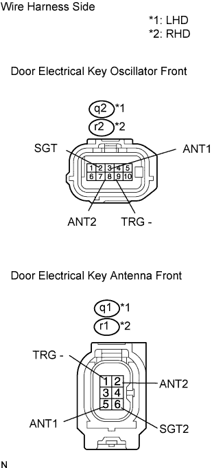
| 8.CHECK WIRE HARNESS (DOOR ELECTRICAL KEY OSCILLATOR FRONT - DOOR ELECTRICAL KEY ANTENNA FRONT) |
Disconnect the q2*1 or r2*2 oscillator connector.
Disconnect the q1*1 or r1*2 antenna connector.
Measure the resistance of the wire harness side connectors.
- Standard resistance:
Tester Connection
| Specified Condition
|
q2-2 (SGT) - q1-6 (SGT2)*1
r2-2 (SGT) - r1-6 (SGT2)*2
| Below 1 Ω
|
q2-3 (ANT1) - q1-5 (ANT1)*1
r2-3 (ANT1) - r1-5 (ANT1)*2
| Below 1 Ω
|
q2-8 (ANT2) - q1-2 (ANT2)*1
r2-8 (ANT2) - r1-2 (ANT2)*2
| Below 1 Ω
|
q2-9 (TRG-) - q1-1 (TRG-)*1
r2-9 (TRG-) - r1-1 (TRG-)*2
| Below 1 Ω
|
| | REPAIR OR REPLACE HARNESS AND CONNECTOR |
|
|
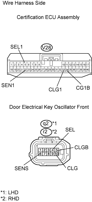
| 9.CHECK WIRE HARNESS (ECU - OSCILLATOR) |
Disconnect the V28 ECU connector.
Disconnect the q2*1 or r2*2 oscillator connector.
Measure the resistance of the wire harness side connectors.
- Standard resistance:
Tester Connection
| Specified Condition
|
V28-5 (SEL1) - q2-4 (SEL)*1
V28-5 (SEL1) - r2-4 (SEL)*2
| Below 1 Ω
|
V28-22 (SEN1) - q2-6 (SENS)*1
V28-22 (SEN1) - r2-6 (SENS)*2
| Below 1 Ω
|
V28-33 (CLG1) - q2-10 (CLG)*1
V28-33 (CLG1) - r2-10 (CLG)*2
| Below 1 Ω
|
V28-34 (CG1B) - q2-5 (CLGB)*1
V28-34 (CG1B) - r2-5 (CLGB)*2
| Below 1 Ω
|
| | REPAIR OR REPLACE HARNESS AND CONNECTOR |
|
|
| OK |
|
|
|
| REPLACE ELECTRICAL KEY OSCILLATOR FRONT |
|