Entry And Start System -- Terminals Of Ecu |
| CHECK CERTIFICATION ECU |
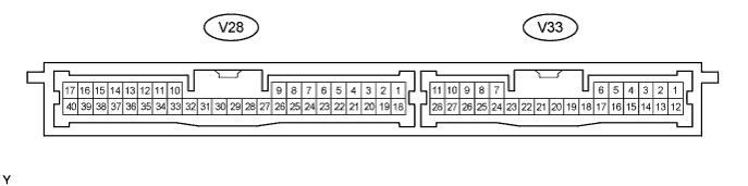
Disconnect the V28 ECU connector.
Measure the voltage and resistance of the wire harness side connector.
Symbols (Terminal No.) Wiring Color Terminal Description Condition Specified Condition +B1 (V28-1) - Body ground R - Body ground +B power supply Always 10 to 14 V IG (V28-18) - Body ground B - Body ground Ignition power supply Engine switch off Below 1 V IG (V28-18) - Body ground B - Body ground Ignition power supply Engine switch on (IG) 10 to 14 V E (V28-17) - Body ground W-B - Body ground Ground Always Below 1 Ω - If the result is not as specified, the wire harness side may have a malfunction.
- If the result is not as specified, the wire harness side may have a malfunction.
Reconnect the V28 ECU connector.
Measure the voltage of the connectors.
Symbols (Terminal No.) Wiring Color Terminal Description Condition Specified Condition CLG1 (V28-33) - CG1B (V28-34) W - R Door electrical key oscillator (front LH) sensor signal All doors closed, all doors locked and engine switch off Alternating between 5 V and below 1 V CLG1 (V28-33) - CG1B (V28-34) W - R Door electrical key oscillator (front LH) sensor signal Door unlocked or door open Below 1 V SEN1 (V28-22) - E (V28-17) V - W-B Touch sensor detection signal Outside door handle touched 10 to 14 V SEN1 (V28-22) - E (V28-17) V - W-B Touch sensor detection signal Outside door handle not touched Below 1 V SEL1 (V28-5) - E (V28-17) B - W-B Touch sensor activation control signal Key at least 3 m (9.8 ft.) away from door 10 to 14 V SEL1 (V28-5) - E (V28-17) B - W-B Touch sensor activation control signal Close to door Below 1 V CLG2 (V28-35) - CG2B (V28-36) B - W*1
W - R*2Door electrical key oscillator (front RH) sensor signal All doors closed, all doors locked and engine switch off Alternating between 5 V and below 1 V CLG2 (V28-35) - CG2B (V28-36) B - W*1
W - R*2Door electrical key oscillator (front RH) sensor signal Door unlocked or door open Below 1 V SEN2 (V28-23) - E (V28-17) R - W-B*1
V - W-B*2Touch sensor detection signal Outside door handle touched 10 to 14 V SEN2 (V28-23) - E (V28-17) R - W-B*1
V - W-B*2Touch sensor detection signal Outside door handle not touched Below 1 V SEL2 (V28-6) - E (V28-17) G - W-B*1
B - W-B*2Touch sensor activation control signal Key at least 3 m (9.8 ft.) away from door 10 to 14 V SEL2 (V28-6) - E (V28-17) G - W-B*1
B - W-B*2Touch sensor activation control signal Close to door Below 1 V CLG3 (V33-8) - CG3B (V28-9) R - W*1
B - Y*2Door electrical key oscillator (rear LH) sensor signal All doors closed, all doors locked and engine switch off Alternating between 5 V and below 1 V CLG3 (V33-8) - CG3B (V28-9) R - W*1
B - Y*2Door electrical key oscillator (rear LH) sensor signal Door unlocked or door open Below 1 V SEN3 (V33-28) - E (V28-17) BR - W-B*1
SB - W-B*2Touch sensor detection signal Outside door handle touched 10 to 14 V SEN3 (V33-28) - E (V28-17) BR - W-B*1
SB - W-B*2Touch sensor detection signal Outside door handle not touched Below 1 V SEL3 (V33-1) - E (V28-17) O - W-B*1
LG - W-B*2Touch sensor activation control signal Key at least 3 m (9.8 ft.) away from door 10 to 14 V SEL3 (V33-1) - E (V28-17) O - W-B*1
LG - W-B*2Touch sensor activation control signal Close to door Below 1 V CLG4 (V33-10) - CG4B (V33-11) B - Y*1
R - W*2Door electrical key oscillator (rear RH) sensor signal All doors closed, all doors locked and engine switch off Alternating between 5 V and below 1 V CLG4 (V33-10) - CG4B (V33-11) B - Y*1
R - W*2Door electrical key oscillator (rear RH) sensor signal Door unlocked or door open Below 1 V SEN4 (V33-27) - E (V28-17) O - W-B*1
BR - W-B*2Touch sensor detection signal Outside door handle touched 10 to 14 V SEN4 (V33-27) - E (V28-17) O - W-B*1
BR - W-B*2Touch sensor detection signal Outside door handle not touched Below 1 V SEL4 (V33-2) - E (V28-17) LG - W-B*1
O - W-B*2Touch sensor activation control signal Key at least 3 m (9.8 ft.) away from door 10 to 14 V SEL4 (V33-2) - E (V28-17) LG - W-B*1
O - W-B*2Touch sensor activation control signal Close to door Below 1 V CLG5 (V28-11) - CG5B (V28-12) GR - BR Indoor electrical key oscillator (front) sensor signal 30 seconds after driver side door opened and closed, engine switch off Alternating between 5 V and below 1 V CLG5 (V28-11) - CG5B (V28-12) GR - BR Indoor electrical key oscillator (front) sensor signal Within 30 seconds driver side door opened and closed, engine switch off Below 1 V CLG6 (V28-13) - CG6B (V28-14) Y - L Indoor electrical key oscillator (rear) sensor signal 30 seconds after driver side door opened and closed, engine switch off Alternating between 5 V and below 1 V CLG6 (V28-13) - CG6B (V28-14) Y - L Indoor electrical key oscillator (rear) sensor signal Within 30 seconds driver side door opened and closed, engine switch off Below 1 V CLG7 (V28-15) - CG7B (V28-16) P - V Luggage electrical key oscillator (inner) sensor signal Luggage compartment door opening switch OFF Alternating between 5 V and below 1 V CLG7 (V28-15) - CG7B (V28-16) P - V Luggage electrical key oscillator (inner) sensor signal Luggage compartment door opening switch ON Below 1 V CLG8 (V28-31) - CG8B (V28-32) L - LG Luggage electrical key oscillator (outer) sensor signal Luggage compartment door opening switch OFF Alternating between 5 V and below 1 V CLG8 (V28-31) - CG8B (V28-32) L - LG Luggage electrical key oscillator (outer) sensor signal Luggage compartment door opening switch ON Below 1 V RCO (V28-29) - E (V28-17) P - W-B Entry door control receiver power source All doors closed, all doors locked and engine switch off 0 to 6 V RCO (V28-29) - E (V28-17) P - W-B Entry door control receiver power source Door unlocked or door open Below 1 V RSSI (V28-39) - E (V28-17) O - W-B Entry door control receiver electric wave existence signal All doors closed, all doors locked and engine switch off 0 to 5 V RSSI (V28-39) - E (V28-17) O - W-B Entry door control receiver electric wave existence signal Door unlocked or door open Below 1 V RDA (V28-38) - E (V28-17) G - W-B Entry door control receiver data input signal All doors closed, all doors locked and engine switch off Below 1 V RDA (V28-38) - E (V28-17) G - W-B Entry door control receiver data input signal Door unlocked or door open Approx. 6 to 7 V - HINT:
- *1: LHD
- *2: RHD
- If the result is not as specified, the ECU may have a malfunction.
| CHECK COWL SIDE JUNCTION BLOCK RH ASSEMBLY (MULTIPLEX NETWORK BODY ECU) |
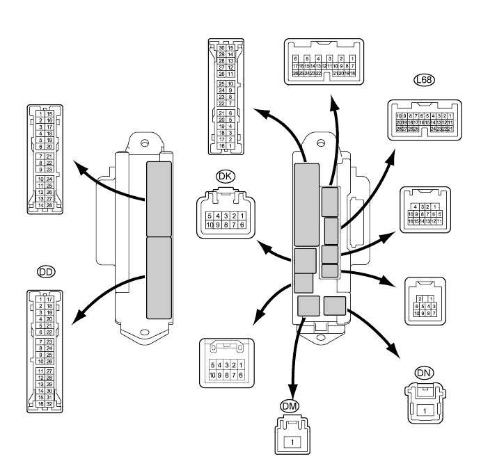
Disconnect the DD, DK, DM and DN junction block connectors.
Measure the voltage and resistance of the wire harness side connectors.
Symbols (Terminal No.) Wiring Color Terminal Description Condition Specified Condition BECU (DK-5) - Body ground G-R - Body ground +B (ECUB) engine supply Always 10 to 14 V ALTB (DM-1) - Body ground B - Body ground +B (power system, generator system) power supply Always 10 to 14 V BATB (DN-1) - Body ground R - Body ground +B (power system, generator system) power supply Always 10 to 14 V GND2 (DD-7) - Body ground W-B - Body ground Ground Always Below 1 Ω - If the result is not as specified, the wire harness side may have a malfunction.
- If the result is not as specified, the wire harness side may have a malfunction.
Reconnect the DD, DK, DM and DN junction block connectors.
Measure the resistance of the connectors.
Symbols (Terminal No.) Wiring Color Terminal Description Condition Specified Condition TSW (L68-2) - GND2 (DD-7) BR - W-B Luggage compartment door opener cancel switch signal Luggage compartment door opener cancel switch not pushed 10 kΩ or higher TSW (L68-2) - GND2 (DD-7) BR - W-B Luggage compartment door opener cancel switch signal Luggage compartment door opener cancel switch pushed Below 1 Ω - If the result is not as specified, the junction block may have a malfunction.
- If the result is not as specified, the junction block may have a malfunction.
| CHECK MULTIPLEX NETWORK DOOR ECU FRONT LH |
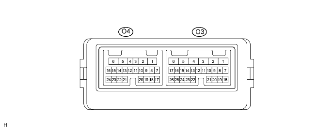
Disconnect the O3 and O4 ECU connectors.
Measure the resistance and voltage of the wire harness side connectors.
Symbols (Terminal No.) Wiring Color Terminal Description Condition Specified Condition GND (O3-1) - Body ground W-B - Body ground Ground Always Below 1 Ω CPUB (O3-4) - GND (O3-1) LG - W-B*1
G - W-B*2CPUB power supply Always 10 to 14 V BDR (O3-6) - GND (O3-1) L - W-B BDR power supply Always 10 to 14 V SIG (O3-3) - GND (O3-1) Y - W-B IG power supply Engine switch on (IG) 10 to 14 V TRG+ (O4-18) - GND (O3-1) L - W-B Lock switch signal Lock switch not pushed 10 kΩ or higher TRG+ (O4-18) - GND (O3-1) L - W-B Lock switch signal Lock switch pushed Below 1 Ω - HINT:
- *1: LHD
- *2: RHD
- If the result is not as specified, the wire harness side may have a malfunction.
Reconnect the O3 and O4 connectors.
Measure the voltage of the connectors.
Symbols (Terminal No.) Wiring Color Terminal Description Condition Specified Condition OSCB (O4-7) - OSCE (O4-20) SB - G*1
R - G*2Power source supply Always 10 to 14 V - HINT:
- *1: LHD
- *2: RHD
- If the result is not as specified, the ECU may have a malfunction.
| CHECK MULTIPLEX NETWORK DOOR ECU FRONT RH |
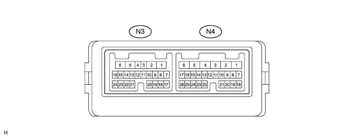
Disconnect the N3 and N4 ECU connectors.
Measure the resistance and voltage of the wire harness side connectors.
Symbols (Terminal No.) Wiring Color Terminal Description Condition Specified Condition GND (N4-1) - Body ground W-B - Body ground Ground Always Below 1 Ω CPUB (N4-4) - GND (N4-1) LG - W-B*1
B - W-B*2CPUB power supply Always 10 to 14 V BDR (N4-6) - GND (N4-1) L - W-B*1
R - W-B*2BDR power supply Always 10 to 14 V SIG (N4-3) - GND (N4-1) L - W-B*1
O - W-B*2IG power supply Engine switch on (IG) 10 to 14 V TRG+ (N3-18) - GND (N4-1) L - W-B Lock switch signal Lock switch not pushed 10 kΩ or higher TRG+ (N3-18) - GND (N4-1) L - W-B Lock switch signal Lock switch pushed Below 1 Ω - HINT:
- *1: LHD
- *2: RHD
- If the result is not as specified, the wire harness side may have a malfunction.
Reconnect the N3 and N4 connectors.
Measure the voltage of the connector.
Symbols (Terminal No.) Wiring Color Terminal Description Condition Specified Condition OSCB (N3-7) - OSCE (N3-20) R - G Power source supply Always 10 to 14 V - If the result is not as specified, the ECU may have a malfunction.
- If the result is not as specified, the ECU may have a malfunction.
| CHECK MULTIPLEX NETWORK DOOR ECU REAR LH |

Disconnect the Q2 and Q3 ECU connectors.
Measure the resistance and voltage of the wire harness side connectors.
Symbols (Terminal No.) Wiring Color Terminal Description Condition Specified Condition GND (Q2-1) - Body ground W-B - Body ground Ground Always Below 1 Ω CPUB (Q2-4) - GND (Q2-1) BR - W-B CPUB power supply Always 10 to 14 V BDR (Q2-6) - GND (Q2-1) L - W-B BDR power supply Always 10 to 14 V SIG (Q2-3) - GND (Q2-1) G - W-B IG power supply Engine switch on (IG) 10 to 14 V TRG+ (Q3-18) - GND (Q2-1) L - W-B Lock switch signal Lock switch not pushed 10 kΩ or higher TRG+ (Q3-18) - GND (Q2-1) L - W-B Lock switch signal Lock switch pushed Below 1 Ω - If the result is not as specified, the wire harness side may have a malfunction.
- If the result is not as specified, the wire harness side may have a malfunction.
Reconnect the Q2 and Q3 connectors.
Measure the voltage of the connector.
Symbols (Terminal No.) Wiring Color Terminal Description Condition Specified Condition OSCB (Q3-7) - OSCE (Q3-20) R - G Power source supply Always 10 to 14 V - If the result is not as specified, the ECU may have a malfunction.
- If the result is not as specified, the ECU may have a malfunction.
| CHECK MULTIPLEX NETWORK DOOR ECU REAR RH |
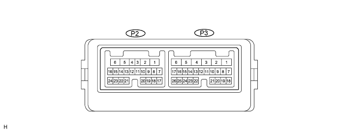
Disconnect the P2 and P3 ECU connectors.
Measure the resistance and voltage of the wire harness side connectors.
Symbols (Terminal No.) Wiring Color Terminal Description Condition Specified Condition GND (P3-1) - Body ground W-B - Body ground Ground Always Below 1 Ω CPUB (P3-4) - GND (P3-1) G - W-B CPUB power supply Always 10 to 14 V BDR (P3-6) - GND (P3-1) L - W-B BDR power supply Always 10 to 14 V SIG (P3-3) - GND (P3-1) L - W-B IG power supply Engine switch on (IG) 10 to 14 V TRG+ (P2-18) - GND (P3-1) L - W-B Lock switch signal Lock switch not pushed 10 kΩ or higher TRG+ (P2-18) - GND (P3-1) L - W-B Lock switch signal Lock switch pushed Below 1 Ω - If the result is not as specified, the wire harness side may have a malfunction.
- If the result is not as specified, the wire harness side may have a malfunction.
Reconnect the P2 and P3 connectors.
Measure the voltage of the connector.
Symbols (Terminal No.) Wiring Color Terminal Description Condition Specified Condition OSCB (P2-7) - OSCE (P2-20) R - G Power source supply Always 10 to 14 V - If the result is not as specified, the ECU may have a malfunction.
- If the result is not as specified, the ECU may have a malfunction.
| CHECK NO. 1 JUNCTION BLOCK ASSEMBLY (MULTIPLEX NETWORK REAR ECU) |
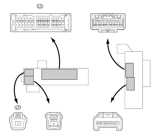
Disconnect the LC and LF junction block connectors.
Measure the resistance and voltage of the wire harness side connectors.
Symbols (Terminal No.) Wiring Color Terminal Description Condition Specified Condition ECUB (LC-15) - Body ground B - Body ground +B power supply Always 10 to 14 V PGND (LF-1) - Body ground W-B - Body ground Ground Always Below 1 Ω SG (LC-3) - Body ground W-B - Body ground Ground Always Below 1 Ω - If the result is not as specified, the wire harness side may have a malfunction.
- If the result is not as specified, the wire harness side may have a malfunction.