Wireless Door Lock Control System No Answer-Back (Hazard Warning Light And Wireless Door Lock Buzzer)
SYSTEM DESCRIPTION
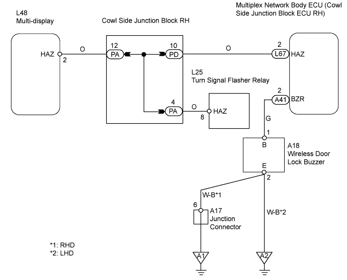
WIRING DIAGRAM
INSPECTION PROCEDURE
CHECK WIRELESS DOOR LOCK
CHECK HAZARD WARNING LIGHTS
PERFORM ACTIVE TEST (HAZARD WARNING LIGHT)
CHECK WIRE HARNESS (MULTIPLEX NETWORK BODY ECU - TURN SIGNAL FLASHER RELAY)
PERFORM ACTIVE TEST (WIRELESS DOOR LOCK BUZZER)
CHECK WIRE HARNESS (WIRELESS DOOR LOCK BUZZER - MULTIPLEX NETWORK BODY ECU AND BODY GROUND)
REPLACE WIRELESS DOOR LOCK BUZZER
WIRELESS DOOR LOCK CONTROL SYSTEM - No Answer-Back (Hazard Warning Light and Wireless Door Lock Buzzer) |
SYSTEM DESCRIPTION
In some cases, wireless control functions are normal but the hazard warning lights and wireless door lock buzzer are not. Malfunctions may be present in the cowl side junction block ECU's hazard warning light and wireless door lock buzzer signal outputs.
WIRING DIAGRAM
INSPECTION PROCEDURE
| 1.CHECK WIRELESS DOOR LOCK |
Check that the wireless door lock functions operate with the transmitter.
ResultFunction
| Proceed to
|
Wireless door lock functions operate normally but hazard warning light answer-back does not occur
| A
|
Wireless door lock functions operate normally but wireless door lock buzzer answer-back does not occur
| B
|
Wireless door lock functions do not operate
| C
|
| |
|
| | GO TO PROBLEM SYMPTOMS TABLE |
|
|
| 2.CHECK HAZARD WARNING LIGHTS |
Check that the hazard warning lights flash continuously when hazard warning switch is pressed.
- OK:
- Hazard warning lights flash continuously.
| 3.PERFORM ACTIVE TEST (HAZARD WARNING LIGHT) |
Select the Active Test, use the intelligent tester to generate a control command, and then check that the hazard warning lights flash.
Multiplex network body ECUItem
| Test Details
| Diagnostic Note
|
Hazard
| Turn signal flasher relay ON / OFF
| -
|
- OK:
- Hazard warning lights flash.
| OK |
|
|
|
| REPLACE COWL SIDE JUNCTION BLOCK RH (MULTIPLEX NETWORK BODY ECU) |
|
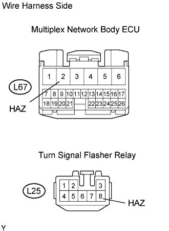
| 4.CHECK WIRE HARNESS (MULTIPLEX NETWORK BODY ECU - TURN SIGNAL FLASHER RELAY) |
Disconnect the L67 ECU connector.
Disconnect the L25 relay connector.
Measure the resistance of the wire harness side connectors.
- Standard resistance:
Tester Connection
| Specified Condition
|
L67-2 (HAZ) - L25-8 (HAZ)
| Below 1 Ω
|
| | REPAIR OR REPLACE HARNESS AND CONNECTOR |
|
|
| OK |
|
|
|
| REPLACE COWL SIDE JUNCTION BLOCK RH (MULTIPLEX NETWORK BODY ECU) |
|
| 5.PERFORM ACTIVE TEST (WIRELESS DOOR LOCK BUZZER) |
Select the Active Test, use the intelligent tester to generate a control command, and then check that the wireless door lock buzzer sounds.
- Multiplex Network Body ECU:
Item
| Test Details
| Diagnostic Note
|
Buzzer Resp Sound
| Wireless door lock buzzer ON / OFF
| -
|
- OK:
- Wireless door lock buzzer sounds.
| OK |
|
|
|
| REPLACE COWL SIDE JUNCTION BLOCK RH (MULTIPLEX NETWORK BODY ECU) |
|
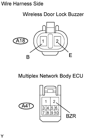
| 6.CHECK WIRE HARNESS (WIRELESS DOOR LOCK BUZZER - MULTIPLEX NETWORK BODY ECU AND BODY GROUND) |
Disconnect the A18 buzzer connector.
Disconnect the A41 ECU connector.
Measure the resistance of the wire harness side connectors.
- Standard resistance:
Tester Connection
| Specified Condition
|
A18-1 (B) - A41-2 (BZR)
| Below 1 Ω
|
A18-2 (E) - Body ground
| Below 1 Ω
|
A18-1 (B) - Body ground
| 10 kΩ or higher
|
| | REPAIR OR REPLACE HARNESS AND CONNECTOR |
|
|
| 7.REPLACE WIRELESS DOOR LOCK BUZZER |
After replacing the wireless door lock buzzer with a normal one, check that the wireless door lock buzzer sounds by using the transmitter LOCK / UNLOCK switch.
- OK:
- Wireless door lock buzzer sounds.
| | REPLACE COWL SIDE JUNCTION BLOCK RH (MULTIPLEX NETWORK BODY ECU) |
|
|