Wireless Door Lock Control System Only Wireless Control Function Is Inoperative
SYSTEM DESCRIPTION
WIRING DIAGRAM
INSPECTION PROCEDURE
CHECK WIRELESS DOOR LOCK
CHECK THAT TRANSMITTER LED ILLUMINATES
CHECK WIRELESS DOOR LOCK CONTROL FUNCTIONS (STANDARD OPERATION)
REPLACE TRANSMITTER BATTERY
CHECK CERTIFICATION ECU ASSEMBLY
CHECK WIRE HARNESS (CERTIFICATION ECU - DOOR CONTROL RECEIVER AND BODY GROUND)
CHECK DOOR CONTROL RECEIVER (OUTPUT)
WIRELESS DOOR LOCK CONTROL SYSTEM - Only Wireless Control Function is inoperative |
SYSTEM DESCRIPTION
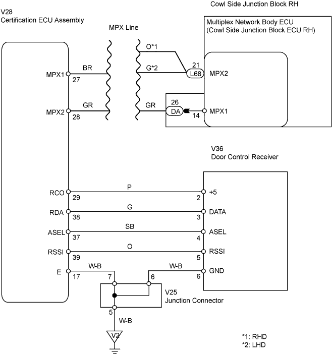
The door control receiver receives a signal from the transmitter and send signals to the multiplex network body ECU through the certification ECU assembly. The multiplex network body ECU then controls all doors by sending LOCK/UNLOCK signals to each door ECU, hazard flasher relay operation signals to the turn signals flasher relay (hazard warning lights) and wireless door lock buzzer sound signals to the wireless door lock buzzer.
WIRING DIAGRAM
INSPECTION PROCEDURE
| 1.CHECK WIRELESS DOOR LOCK |
| 2.CHECK THAT TRANSMITTER LED ILLUMINATES |
Check that the transmitter's LED illuminates 3 times when the switch is pressed 3 times.
- OK:
- Transmitter's LED illuminates 3 times when the switch is pressed 3 times.
| 3.CHECK WIRELESS DOOR LOCK CONTROL FUNCTIONS (STANDARD OPERATION) |
Check standard LOCK/UNLOCK switch operation.
- NOTICE:
- Standardized test procedure: press the transmitter switch for 1 second, directing the beam to the driver side door outside handle from a distance of 1 m (3.28 ft). The transmitter should be pointed directly at the handle, i.e. at a 90° angle to the vehicle body.
| OK |
|
|
|
| REPLACE DOOR CONTROL RECEIVER |
|
| 4.REPLACE TRANSMITTER BATTERY |
After replacing the transmitter battery, check that the doors can be locked and unlocked by using the transmitter LOCK/UNLOCK switch.
- OK:
- Doors can be locked and unlocked with transmitter.
| | REPLACE DOOR CONTROL TRANSMITTER |
|
|
| 5.CHECK CERTIFICATION ECU ASSEMBLY |
Reconnect the V28 ECU connector.
Measure the voltage of the wire harness side connector.
- Standard voltage:
Tester Connection
| Specified Condition
|
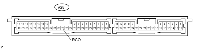
V28-29 (RCO) - Body ground
| 4.6 to 5.4 V
|
| | REPLACE CERTIFICATION ECU ASSEMBLY |
|
|
| 6.CHECK WIRE HARNESS (CERTIFICATION ECU - DOOR CONTROL RECEIVER AND BODY GROUND) |
Disconnect the V36 receiver connector.
Disconnect the V28 ECU connector.
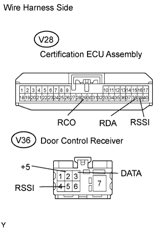
Measure the resistance of the wire harness side connectors.
- Standard resistance:
Tester Connection
| Specified Condition
|
V28-39 (RSSI) - V36-5 (RSSI)
| Below 1 Ω
|
V28-38 (RDA) - V36-3 (DATA)
| Below 1 Ω
|
V28-29 (RCO) - V36-2 (+5)
| Below 1 Ω
|
V28-39 (RSSI) - Body ground
| 10 KΩ or higher
|
V28-38 (RDA) - Body ground
| 10 KΩ or higher
|
| | REPLACE CERTIFICATION ECU ASSEMBLY |
|
|
| 7.CHECK DOOR CONTROL RECEIVER (OUTPUT) |
Reconnect the V36 receiver connector.
Measure the voltage between the terminal of the connector and body ground.
- Standard voltage:
Tester Connection
| Condition
| Specified Condition
|
V36-3 (DATA) - Body ground
| Engine switch off, all doors closed and transmitter switch not pressed
| 10 to 14 V
|
V36-3 (DATA) - Body ground
| Engine switch off, all doors closed and transmitter switch pressed
| Pulse generation
|
| | REPLACE DOOR CONTROL RECEIVER |
|
|
| OK |
|
|
|
| REPLACE CERTIFICATION ECU ASSEMBLY |
|