Body Electrical. Lexus Gs430, Gs300. Uzs190 Grs190
Door Lock. Lexus Gs430, Gs300. Uzs190 Grs190
Wireless Door Lock Control System -- Terminals Of Ecu |
| CHECK COWL SIDE JUNCTION BLOCK RH ASSEMBLY (MULTIPLEX NETWORK BODY ECU) |
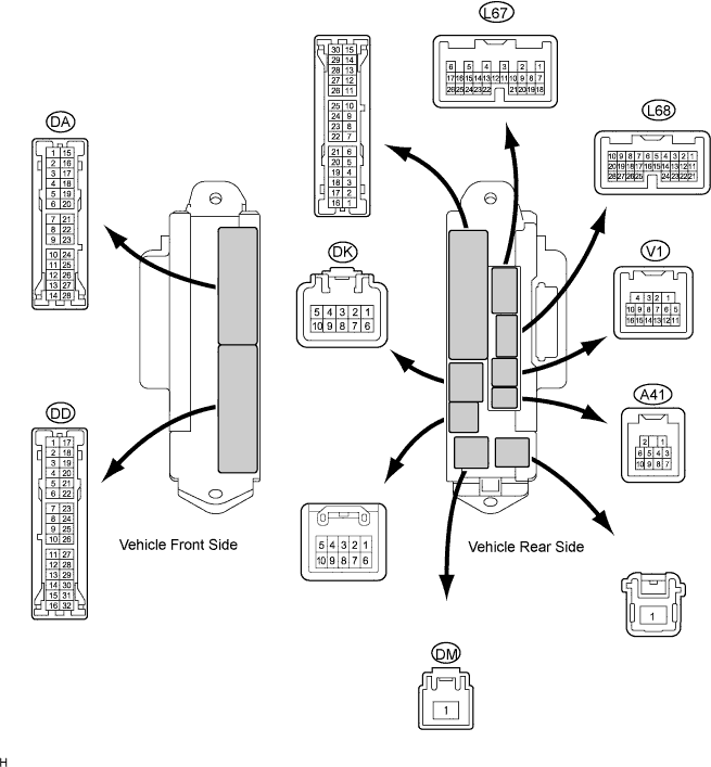
Disconnect the DA, DD, DK and DM junction block connectors.
Disconnect the L68 and V1 ECU connectors.
Measure the resistance and voltage of the wire harness side connectors.
Symbols (Terminal No.) Wiring Color Terminal Description Condition Specified Condition BECU (DK-5) - GND2 (DD-7) G-R - W-B BECU power supply Always 10 to 14 V ACC (DM-1) - GND2 (DD-7) B - W-B ACC power supply Always 10 to 14 V IG (DM-1) - GND2 (DD-7) B - W-B IG power supply Always 10 to 14 V DCTY (V1-14) - Body ground R - Body ground Driver side door courtesy light switch input Driver side door open Below 1 Ω DCTY (V1-14) - Body ground R - Body ground Driver side door courtesy light switch input Driver side door closed 10 kΩor higher PCTY (L68-23) - Body ground R - Body ground Passenger side door courtesy light switch input Passenger side door open Below 1 Ω PCTY (L68-23) - Body ground R - Body ground Passenger side door courtesy light switch input Passenger side door closed 10 kΩor higher RCTY (V1-16) - Body ground L - Body ground Rear RH side door courtesy light switch input Rear RH side door open Below 1 Ω RCTY (V1-16) - Body ground L - Body ground Rear RH side door courtesy light switch input Rear RH side door closed 10 kΩor higher LCTY (DA-11) - Body ground G - Body ground Rear LH side door courtesy light switch input Rear LH side door open Below 1 Ω LCTY (DA-11) - Body ground G - Body ground Rear LH side door courtesy light switch input Rear LH side door closed 10 kΩor higher GND2 (DD-7) - Body ground W-B - Body ground Ground Always Below 1 Ω GND2 (DA-5) - Body ground W-B - Body ground Ground Always Below 1 Ω - If the result is not as specified, there may be a malfunction on the wire harness side.
- If the result is not as specified, there may be a malfunction on the wire harness side.
Reconnect the DA, DD, DK and DM junction connectors.
Reconnect the L68 and V1 ECU connectors.
Measure the voltage of the wire harness side connectors.
| Symbols (Terminal No.) | Wiring Color | Terminal Description | Condition | Specified Condition |
| HAZ (L67-2) - Body ground | O - Body ground | Hazard warning light drive | Answer-back ON | Pulse generation |
| HAZ (L67-2) - Body ground | O - Body ground | Hazard warning light drive | Answer-back OFF | 10 to 14 V |
| BZR (A41-2) - Body ground | G - Body ground | Wireless warning buzzer drive | Answer-back ON | Pulse generation |
| BZR (A41-2) - Body ground | G - Body ground | Wireless warning buzzer drive | Answer-back OFF | 10 to 14 V |
- If the result is not as specified, the junction block (ECU) may have a malfunction.
| CHECK CERTIFICATION ECU ASSEMBLY |

Disconnect the V28 ECU connector.
Measure the voltage and resistance of the wire harness side connector.
Symbols (Terminal No.) Wiring Color Terminal Description Condition Specified Condition +B1 (V28-1) - E (V28-17) G - W-B Battery power supply Always 10 to 14 V IG (V28-18) - E (V28-17) B - W-B IG power supply Engine switch on (IG) 10 to 14 V IG (V28-18) - E (V28-17) B - W-B IG power supply Engine switch off Below 1 V E (V28-17) - Body ground W-B - Body ground Ground Always Below 1 Ω - If the result is not as specified, there may be a malfunction on the wire harness side.
- If the result is not as specified, there may be a malfunction on the wire harness side.
Reconnect the V28 ECU connector.
Measure the voltage of the connector.
Symbols (Terminal No.) Wiring Color Terminal Description Condition Specified Condition RSS1 (V28-39) - E (V28-17) O - W-B Door control receiver output signal Engine switch off, all doors closed and transmitter switch not pressed 10 to 14 V RSS1 (V28-39) - E (V28-17) O - W-B Door control receiver output signal Engine switch off, all doors closed and transmitter switch pressed Below 1 V RDA (V28-38) - E (V28-17) LG - W-B Door control receiver output signal Engine switch off, all doors closed and transmitter switch not pressed 10 to 14 V RDA (V28-38) - E (V28-17) LG - W-B Door control receiver output signal Engine switch off, all doors closed and transmitter switch pressed Pulse generation - If the result is not as specified, the ECU may have a malfunction.
- If the result is not as specified, the ECU may have a malfunction.