DESCRIPTION
WIRING DIAGRAM
INSPECTION PROCEDURE
CHECK WIRELESS DOOR LOCK CONTROL SYSTEM
PERFORM ACTIVE TEST BY INTELLIGENT TESTER (DOUBLE DOOR LOCK MOTOR)
PERFORM ACTIVE TEST BY INTELLIGENT TESTER (DOUBLE DOOR LOCK MOTOR)
PERFORM ACTIVE TEST BY INTELLIGENT TESTER (DOUBLE DOOR LOCK MOTOR)
PERFORM ACTIVE TEST BY INTELLIGENT TESTER (DOUBLE DOOR LOCK MOTOR)
INSPECT FRONT DOOR LOCK ASSEMBLY (DRIVER SIDE) (DOUBLE DOOR LOCK MOTOR)
READ VALUE OF INTELLIGENT TESTER (DOUBLE DOOR LOCK POSITION SWITCH)
INSPECT FRONT DOOR LOCK ASSEMBLY (DRIVER SIDE) (DOUBLE DOOR LOCK POSITION SWITCH)
CHECK WIRE HARNESS (DRIVER DOOR ECU - FRONT DOOR LOCK ASSEMBLY (DRIVER SIDE))
INSPECT FRONT DOOR LOCK ASSEMBLY (PASSENGER SIDE) (DOUBLE DOOR LOCK MOTOR)
READ VALUE OF INTELLIGENT TESTER (DOUBLE DOOR LOCK POSITION SWITCH)
INSPECT FRONT DOOR LOCK ASSEMBLY (PASSENGER SIDE) (DOUBLE DOOR LOCK POSITION SWITCH)
CHECK WIRE HARNESS (PASSENGER DOOR ECU - FRONT DOOR LOCK ASSEMBLY)
INSPECT REAR DOOR LOCK ASSEMBLY LH (DOUBLE DOOR LOCK MOTOR)
READ VALUE OF INTELLIGENT TESTER (DOUBLE DOOR LOCK POSITION SWITCH)
INSPECT REAR DOOR LOCK ASSEMBLY LH (DOUBLE DOOR LOCK POSITION SWITCH)
CHECK WIRE HARNESS (REAR DOOR LH ECU - REAR DOOR LOCK ASSEMBLY LH)
INSPECT REAR DOOR LOCK ASSEMBLY RH (DOUBLE DOOR LOCK MOTOR)
READ VALUE OF INTELLIGENT TESTER (DOUBLE DOOR LOCK POSITION SWITCH)
INSPECT REAR DOOR LOCK ASSEMBLY RH (DOUBLE DOOR LOCK POSITION SWITCH)
CHECK WIRE HARNESS (REAR DOOR RH ECU - REAR DOOR LOCK ASSEMBLY RH)
POWER DOOR LOCK CONTROL SYSTEM - Double Lock Function does not Operate Properly |
DESCRIPTION
All the doors except the luggage compartment door have the double lock function. This system is set and unset by the multiplex network body ECU. When the multiplex network body ECU receives a request signal from the wireless transmitter to set or unset the double lock function, it drives the double lock motor built into each door lock according to the conditions of the double lock position switches, thus causing the double locking system to be set or unset.
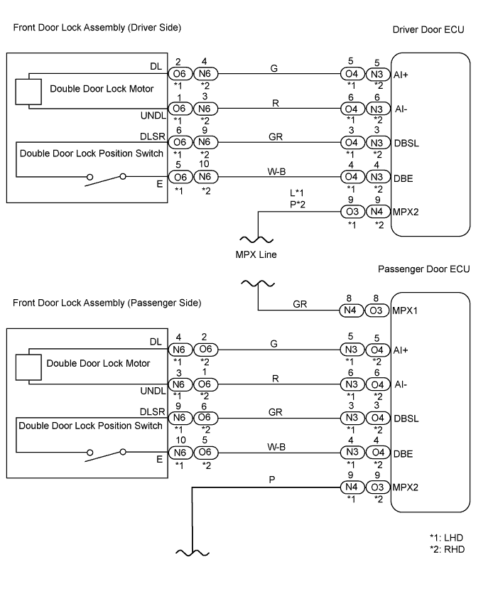
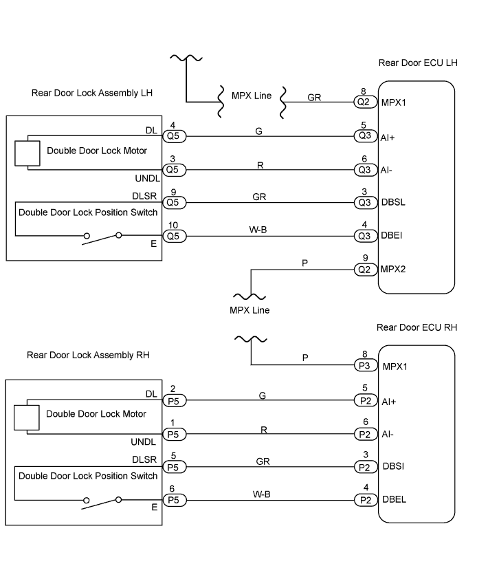
WIRING DIAGRAM
INSPECTION PROCEDURE
| 1.CHECK WIRELESS DOOR LOCK CONTROL SYSTEM |
Check that the doors can be locked and unlocked normally using the wireless operation.
- OK:
- Doors can be locked and unlocked normally using wireless operation.
| | GO TO WIRELESS DOOR LOCK CONTROL SYSTEM |
|
|
| 2.PERFORM ACTIVE TEST BY INTELLIGENT TESTER (DOUBLE DOOR LOCK MOTOR) |
Select the Active Test, use the intelligent tester to generate a control command, and then check that the double door lock motor operates normally.
- Driver door ECU:
Item
| Tester Details
| Diagnostic Note
|
Double Lock Unset
| Operate double lock motor/UNSET or SET
| -
|
- OK:
- Double door lock motor operates normally.
| 3.PERFORM ACTIVE TEST BY INTELLIGENT TESTER (DOUBLE DOOR LOCK MOTOR) |
Select the Active Test, use the intelligent tester to generate a control command, and then check that the double door lock motor operates normally.
- Passenger door ECU:
Item
| Tester Details
| Diagnostic Note
|
Double Lock Unset
| Operate double lock motor/UNSET or SET
| -
|
- OK:
- Double door lock motor operates normally.
| 4.PERFORM ACTIVE TEST BY INTELLIGENT TESTER (DOUBLE DOOR LOCK MOTOR) |
Select the Active Test, use the intelligent tester to generate a control command, and then check that the double door lock motor operates normally.
- Rear door ECU LH:
Item
| Tester Details
| Diagnostic Note
|
Double Lock Unset
| Operate double lock motor/UNSET or SET
| -
|
- OK:
- Double door lock motor operates normally.
| 5.PERFORM ACTIVE TEST BY INTELLIGENT TESTER (DOUBLE DOOR LOCK MOTOR) |
Select the Active Test, use the intelligent tester to generate a control command, and then check that the double door lock motor operates normally.
- Rear door ECU RH:
Item
| Tester Details
| Diagnostic Note
|
Double Lock Unset
| Operate double lock motor/UNSET or SET
| -
|
- OK:
- Double door lock motor operates normally.
| OK |
|
|
|
| REPLACE COWL SIDE JUNCTION BLOCK RH (MULTIPLEX NETWORK BODY ECU) |
|
| 6.INSPECT FRONT DOOR LOCK ASSEMBLY (DRIVER SIDE) (DOUBLE DOOR LOCK MOTOR) |
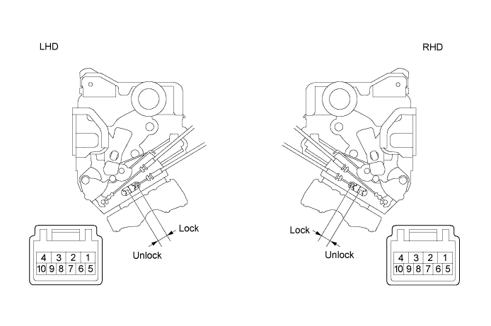
Check operation of the double lock motor.
Apply battery voltage to the door lock and set the door lock motor to the lock position.
- OK :
LHDMeasurement Condition
| Specified Condition
|
Battery positive (+) → Terminal 4
Battery negative (-) → Terminal 3
| Lock
|
Battery positive (+) → Terminal 3
Battery negative (-) → Terminal 4
| Unlock
|
- RHD:
Measurement Condition
| Specified Condition
|
Battery positive (+) → Terminal 2
Battery negative (-) → Terminal 1
| Lock
|
Battery positive (+) → Terminal 1
Battery negative (-) → Terminal 2
| Unlock
|
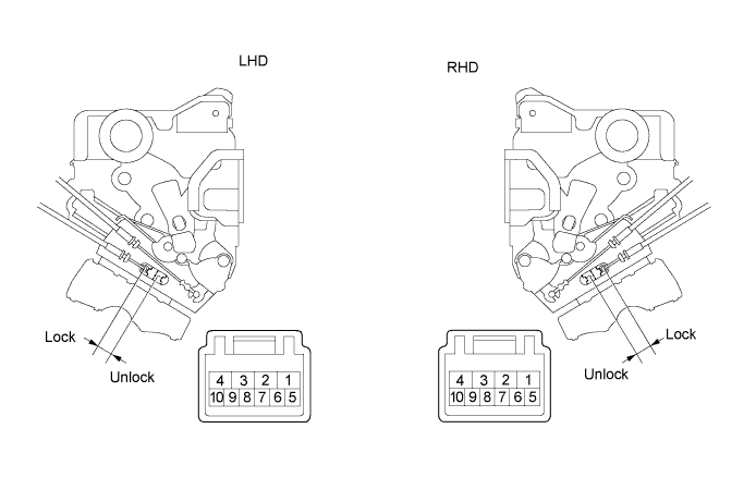
Apply battery voltage to the door lock motor and check the operation of the double door lock motor.
- OK :
LHDMeasurement Condition
| Specified Condition
|
Battery positive (+) → Terminal 2
Battery negative (-) → Terminal 1
| Set
|
Battery positive (+) → Terminal 1
Battery negative (-) → Terminal 2
| Unset
|
- RHD:
Measurement Condition
| Specified Condition
|
Battery positive (+) → Terminal 4
Battery negative (-) → Terminal 3
| Set
|
Battery positive (+) → Terminal 3
Battery negative (-) → Terminal 4
| Unset
|
While the double locking system is set, check that the doors cannot be unlocked by operating the control cable.
| | REPLACE FRONT DOOR LOCK ASSEMBLY |
|
|
| 7.READ VALUE OF INTELLIGENT TESTER (DOUBLE DOOR LOCK POSITION SWITCH) |
Check the Data List for proper functioning of the double door lock position switch.
- Driver door ECU:
Item
| Measurement Item/Display (Range)
| Normal Condition
| Diagnostic Note
|
Double Lock Position SW
| Driver side double door lock position switch signal/ ON or OFF
| ON: Driver side double door is unset
OFF: Driver side double door is set
| -
|
- OK:
- ON (driver side double door is unset) appears on screen.
| 8.INSPECT FRONT DOOR LOCK ASSEMBLY (DRIVER SIDE) (DOUBLE DOOR LOCK POSITION SWITCH) |
Measure the resistance of the double door lock position switch.
- Standard resistance:
LHDTester Connection
| Switch Condition
| Specified Condition
|
5 - 6
| Set
| Below 1 Ω
|
5 - 6
| Unset
| 10 kΩ or higher
|
- RHD:
Tester Connection
| Switch Condition
| Specified Condition
|
9 - 10
| Set
| Below 1 Ω
|
9 - 10
| Unset
| 10 kΩ or higher
|
| | REPLACE FRONT DOOR LOCK ASSEMBLY |
|
|
| 9.CHECK WIRE HARNESS (DRIVER DOOR ECU - FRONT DOOR LOCK ASSEMBLY (DRIVER SIDE)) |
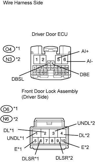
Disconnect the O4*1 or N3*2 ECU connector.
Disconnect the O6*1 or N6*2 door lock connector.
Measure the resistance of the wire harness side connectors.
- Standard resistance:
LHDTester Connection
| Specified Condition
|
O4-5 (AI+) - O6-2 (DL)
| Below 1 Ω
|
O4-6 (AI-) - O6-1 (UNDL)
| Below 1 Ω
|
O4-3 (DBSL) - O6-6 (DLSR)
| Below 1 Ω
|
O4-4 (DBE) - O6-5 (E)
| Below 1 Ω
|
- RHD:
Tester Connection
| Specified Condition
|
N3-5 (AI+) - N6-4 (DL)
| Below 1 Ω
|
N3-6 (AI-) - N6-3 (UNDL)
| Below 1 Ω
|
N3-3 (DBSL) - N6-9 (DLSR)
| Below 1 Ω
|
N3-4 (DBE) - N6-10 (E)
| Below 1 Ω
|
- HINT:
- *1: LHD
- *2: RHD
| | REPAIR OR REPLACE HARNESS AND CONNECTOR |
|
|
| 10.INSPECT FRONT DOOR LOCK ASSEMBLY (PASSENGER SIDE) (DOUBLE DOOR LOCK MOTOR) |
Check operation of the double lock motor.
Apply battery voltage to the door lock and set the door lock motor to the lock position.
- OK:
LHDMeasurement Condition
| Specified Condition
|
Battery positive (+) → Terminal 2
Battery negative (-) → Terminal 1
| Lock
|
Battery positive (+) → Terminal 1
Battery negative (-) → Terminal 2
| Unlock
|
- RHD:
Measurement Condition
| Specified Condition
|
Battery positive (+) → Terminal 4
Battery negative (-) → Terminal 3
| Lock
|
Battery positive (+) → Terminal 3
Battery negative (-) → Terminal 4
| Unlock
|
Apply battery voltage to the door lock motor and check the operation of the double door lock motor.
- OK :
LHDMeasurement Condition
| Specified Condition
|
Battery positive (+) → Terminal 4
Battery negative (-) → Terminal 3
| Set
|
Battery positive (+) → Terminal 3
Battery negative (-) → Terminal 4
| Unset
|
- RHD:
Measurement Condition
| Specified Condition
|
Battery positive (+) → Terminal 2
Battery negative (-) → Terminal 1
| Set
|
Battery positive (+) → Terminal 1
Battery negative (-) → Terminal 2
| Unset
|
While the double locking system is set, check that the doors cannot be unlocked by operating the control cable.
| | REPLACE FRONT DOOR LOCK ASSEMBLY |
|
|
| 11.READ VALUE OF INTELLIGENT TESTER (DOUBLE DOOR LOCK POSITION SWITCH) |
Check the Data List for proper functioning the of double door lock position switch.
- Passenger door ECU:
Item
| Measurement Item/Display (Range)
| Normal Condition
| Diagnostic Note
|
Double Lock Position SW
| Passenger side double door lock position switch signal/ ON or OFF
| ON: Passenger side double door is unset
OFF: Passenger side double door is set
| -
|
- OK:
- ON (passenger side double door is unset) appears on screen.
| 12.INSPECT FRONT DOOR LOCK ASSEMBLY (PASSENGER SIDE) (DOUBLE DOOR LOCK POSITION SWITCH) |
Measure the resistance of the double door lock position switch.
- Standard resistance:
LHDTester Connection
| Switch Condition
| Specified Condition
|
9 - 10
| Set
| Below 1 Ω
|
9 - 10
| Unset
| 10 kΩ or higher
|
- RHD:
Tester Connection
| Switch Condition
| Specified Condition
|
5 - 6
| Set
| Below 1 Ω
|
5 - 6
| Unset
| 10 kΩ or higher
|
| | REPLACE FRONT DOOR LOCK ASSEMBLY |
|
|
| 13.CHECK WIRE HARNESS (PASSENGER DOOR ECU - FRONT DOOR LOCK ASSEMBLY) |
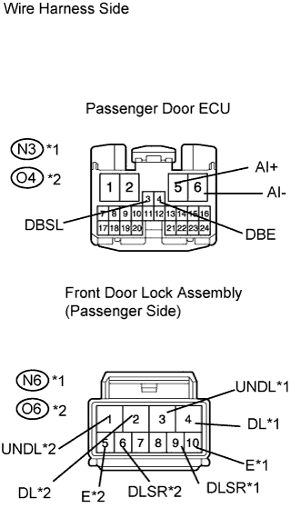
Disconnect the N3*1 or O4*2 ECU connector.
Disconnect the N6*1 or O6*2 door lock connector.
Measure the resistance of the wire harness side connectors.
- Standard resistance:
LHDTester Connection
| Specified Condition
|
N3-5 (AI+) - N6-4 (DL)
| Below 1 Ω
|
N3-6 (AI-) - N6-3 (UNDL)
| Below 1 Ω
|
N3-3 (DBSL) - N6-9 (DLSR)
| Below 1 Ω
|
N3-4 (DBE) - N6-10 (E)
| Below 1 Ω
|
- RHD:
Tester Connection
| Specified Condition
|
O4-5 (AI+) - O6-2 (DL)
| Below 1 Ω
|
O4-6 (AI-) - O6-1 (UNDL)
| Below 1 Ω
|
O4-3 (DBSL) - O6-6 (DLSR)
| Below 1 Ω
|
O4-4 (DBE) - O6-5 (E)
| Below 1 Ω
|
- HINT:
- *1: LHD
- *2: RHD
| | REPAIR OR REPLACE HARNESS AND CONNECTOR |
|
|
| OK |
|
|
|
| REPLACE PASSENGER DOOR ECU |
|
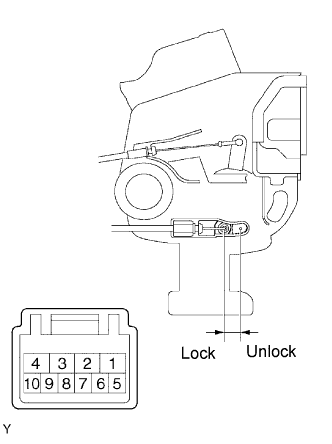
| 14.INSPECT REAR DOOR LOCK ASSEMBLY LH (DOUBLE DOOR LOCK MOTOR) |
Check operation of the double lock motor.
Apply battery voltage to the door lock and set the door lock motor to the lock position.
- OK:
Measurement Condition
| Specified Condition
|
Battery positive (+) → Terminal 4
Battery negative (-) → Terminal 1
| Lock
|
Battery positive (+) → Terminal 1
Battery negative (-) → Terminal 4
| Unlock
|
Apply battery voltage to the door lock motor and check the operation of the double door lock motor.
- OK:
Measurement Condition
| Specified Condition
|
Battery positive (+) → Terminal 4
Battery negative (-) → Terminal 3
| Set
|
Battery positive (+) → Terminal 3
Battery negative (-) → Terminal 4
| Unset
|
While the double locking system is set, check that the doors cannot be unlocked by operating the control cable.
| | REPLACE REAR DOOR LOCK ASSEMBLY LH |
|
|
| 15.READ VALUE OF INTELLIGENT TESTER (DOUBLE DOOR LOCK POSITION SWITCH) |
Check the Data List for proper functioning the of double door lock position switch.
- Rear door ECU LH:
Item
| Measurement Item/Display (Range)
| Normal Condition
| Diagnostic Note
|
Double Lock Position SW
| Rear LH side double door lock position switch signal/ ON or OFF
| ON: Rear LH side double door is unset
OFF: Rear LH side double door is set
| -
|
- OK:
- ON (rear LH side double door is unset) appears on screen.
| 16.INSPECT REAR DOOR LOCK ASSEMBLY LH (DOUBLE DOOR LOCK POSITION SWITCH) |
Measure the resistance of the double door lock position switch.
- Standard resistance:
Tester Connection
| Switch Condition
| Specified Condition
|
9 - 10
| Set
| Below 1 Ω
|
9 - 10
| Unset
| 10 kΩ or higher
|
| | REPLACE REAR DOOR LOCK ASSEMBLY LH |
|
|
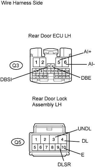
| 17.CHECK WIRE HARNESS (REAR DOOR LH ECU - REAR DOOR LOCK ASSEMBLY LH) |
Disconnect the Q3 ECU connector.
Disconnect the Q5 door lock connector.
Measure the resistance of the wire harness side connectors.
- Standard resistance:
Tester Connection
| Specified Condition
|
Q3-5 (AI+) - Q5-4 (DL)
| Below 1 Ω
|
Q3-6 (AI-) - Q5-3 (UNDL)
| Below 1 Ω
|
Q3-3 (DBSI) - Q5-9 (DLSR)
| Below 1 Ω
|
Q3-4 (DBE) - Q5-10 (E)
| Below 1 Ω
|
| | REPAIR OR REPLACE HARNESS AND CONNECTOR |
|
|
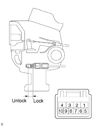
| 18.INSPECT REAR DOOR LOCK ASSEMBLY RH (DOUBLE DOOR LOCK MOTOR) |
Check operation of the double lock motor.
Apply battery voltage to the door lock and set the door lock motor to the lock position.
- OK:
Measurement Condition
| Specified Condition
|
Battery positive (+) → Terminal 4
Battery negative (-) → Terminal 3
| Lock
|
Battery positive (+) → Terminal 3
Battery negative (-) → Terminal 4
| Unlock
|
Apply battery voltage to the door lock motor and check the operation of the double door lock motor.
- OK:
Measurement Condition
| Specified Condition
|
Battery positive (+) → Terminal 2
Battery negative (-) → Terminal 1
| Set
|
Battery positive (+) → Terminal 1
Battery negative (-) → Terminal 2
| Unset
|
While the double locking system is set, check that the doors cannot be unlocked by operating the control cable.
| | REPLACE REAR DOOR LOCK ASSEMBLY RH |
|
|
| 19.READ VALUE OF INTELLIGENT TESTER (DOUBLE DOOR LOCK POSITION SWITCH) |
Check the Data List for proper functioning the of double door lock position switch.
- Rear door ECU RH:
Item
| Measurement Item/Display (Range)
| Normal Condition
| Diagnostic Note
|
Double Lock Position SW
| Rear RH side double door lock position switch signal/ ON or OFF
| ON: Rear RH side double door is unset
OFF: Rear RH side double door is set
| -
|
- OK:
- ON (rear RH side double door is unset) appears on screen.
| 20.INSPECT REAR DOOR LOCK ASSEMBLY RH (DOUBLE DOOR LOCK POSITION SWITCH) |
Measure the resistance of the double door lock position switch.
- Standard resistance:
Tester Connection
| Switch Condition
| Specified Condition
|
5 - 6
| Set
| Below 1 Ω
|
5 - 6
| Unset
| 10 kΩ or higher
|
| | REPLACE REAR DOOR LOCK ASSEMBLY RH |
|
|
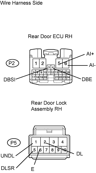
| 21.CHECK WIRE HARNESS (REAR DOOR RH ECU - REAR DOOR LOCK ASSEMBLY RH) |
Disconnect the P2 ECU connector.
Disconnect the P5 door lock connector.
Measure the resistance of the wire harness side connectors.
- Standard resistance:
Tester Connection
| Specified Condition
|
P2-5 (AI+) - P5-2 (DL)
| Below 1 Ω
|
P2-6 (AI-) - P5-1 (UNDL)
| Below 1 Ω
|
P2-3 (DBSI) - P5-5 (DLSR)
| Below 1 Ω
|
P2-4 (DBE) - P5-6 (E)
| Below 1 Ω
|
| | REPAIR OR REPLACE HARNESS AND CONNECTOR |
|
|