Power Door Lock Control System All Doors Lock / Unlock Functions Do Not Operate Via Door Control Switch
DESCRIPTION
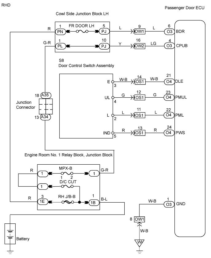
WIRING DIAGRAM
INSPECTION PROCEDURE
INSPECT FUSE (FR DOOR RH*1, FR DOOR LH*2, MPX-B, D/C CUT)
CHECK WIRE HARNESS (PASSENGER DOOR ECU - BATTERY AND BODY GROUND)
INSPECT DOOR CONTROL SWITCH ASSEMBLY
CHECK WIRE HARNESS (DOOR CONTROL SWITCH ASSEMBLY - PASSENGER DOOR ECU)
REPLACE PASSENGER DOOR ECU
POWER DOOR LOCK CONTROL SYSTEM - All Doors LOCK / UNLOCK Functions do not Operate Via Door Control Switch |
DESCRIPTION
The multiplex network body ECU receives switch signals from the door control switch and activates the door lock motor on each door according to the signals.
WIRING DIAGRAM
INSPECTION PROCEDURE
| 1.INSPECT FUSE (FR DOOR RH*1, FR DOOR LH*2, MPX-B, D/C CUT) |
Remove the FR DOOR RH*1 fuse from the cowl side junction block RH.
Remove the FR DOOR LH*2 fuse from the cowl side junction block LH.
Remove the MPX-B and D/C CUT fuses from the engine room No. 1 junction block.
Measure the resistance of the fuses.
- Standard resistance:
- Below 1 Ω
- HINT:
- *1: LHD
- *2: RHD
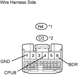
| 2.CHECK WIRE HARNESS (PASSENGER DOOR ECU - BATTERY AND BODY GROUND) |
Disconnect the N4*1 or O3*2 ECU connector.
Measure the voltage of the wire harness side connector.
- Standard voltage:
LHDTester Connection
| Specified Condition
|
N4-6 (BDR) - N4-1 (GND)
| 10 to 14 V
|
N4-4 (CPUB) - N4-1 (GND)
| 10 to 14 V
|
- RHD:
Tester Connection
| Specified Condition
|
O3-6 (BDR) - O3-1 (GND)
| 10 to 14 V
|
O3-4 (CPUB) - O3-1 (GND)
| 10 to 14 V
|
Measure the resistance of the wire harness side connector.
- Standard resistance:
LHDTester Connection
| Specified Condition
|
N4-1 (GND) - Body ground
| Below 1 Ω
|
- RHD:
Tester Connection
| Specified Condition
|
O3-1 (GND) - Body ground
| Below 1 Ω
|
- HINT:
- *1: LHD
- *2: RHD
| | REPAIR OR REPLACE HARNESS AND CONNECTOR |
|
|
| 3.INSPECT DOOR CONTROL SWITCH ASSEMBLY |
Remove the door control switch.
Measure the resistance of the switch.
- Standard resistance:
Tester Connection
| Condition
| Specified Condition
|
2 - 3
| Lock
| Below 1 Ω
|
4 - 3
| Unlock
| Below 1 Ω
|
2 - 3
| Unlock
| 10 kΩ or higher
|
4 - 3
| Lock
| 10 kΩ or higher
|
| | REPLACE DOOR CONTROL SWITCH ASSEMBLY |
|
|
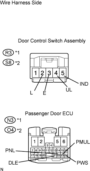
| 4.CHECK WIRE HARNESS (DOOR CONTROL SWITCH ASSEMBLY - PASSENGER DOOR ECU) |
Disconnect the R3*1 or S8*2 switch connector.
Disconnect the N3*1 or O4*2 ECU connector.
Measure the resistance of the wire harness side connectors.
- Standard resistance:
LHDTester Connection
| Specified Condition
|
R3-3 (E) - N3-21 (DLE)
| Below 1 Ω
|
R3-4 (UL) - N3-23 (PMUL)
| Below 1 Ω
|
R3-2 (L) - N3-22 (PNL)
| Below 1 Ω
|
R3-5 (IND) - N3-24 (PWS)
| Below 1 Ω
|
- RHD:
Tester Connection
| Specified Condition
|
S8-3 (E) - O4-21 (DLE)
| Below 1 Ω
|
S8-4 (UL) - O4-23 (PMUL)
| Below 1 Ω
|
S8-2 (L) - O4-22 (PNL)
| Below 1 Ω
|
S8-5 (IND) - O4-24 (PWS)
| Below 1 Ω
|
- HINT:
- *1: LHD
- *2: RHD
| | REPAIR OR REPLACE HARNESS AND CONNECTOR |
|
|
| 5.REPLACE PASSENGER DOOR ECU |
After replacing the passenger door ECU with a normal one, check that all doors can be locked and unlocked by using the door control switch.
- OK:
- All doors can be locked and unlocked with door control switch.
| | REPLACE COWL SIDE JUNCTION BLOCK RH (MULTIPLEX NETWORK BODY ECU) |
|
|
| OK |
|
|
|
| END (PASSENGER DOOR ECU IS FAULTY) |
|