Dtc B1224 Door Lock Switch Circuit On Passenger Door
DESCRIPTION
WIRING DIAGRAM
INSPECTION PROCEDURE
INSPECT DOOR CONTROL SWITCH ASSEMBLY
CHECK WIRE HARNESS (DOOR CONTROL SWITCH ASSEMBLY - PASSENGER DOOR ECU)
DTC B1224 Door Lock Switch Circuit on Passenger Door |
DESCRIPTION
If this DTC is output when not operating the switch, it means that the switch is ON, OFF or stuck. If this DTC is not output when operating the switch, switch contact has failed. When something wrong is found using this diagnosis, inspect each switch. Replace the switch if there is a problem or check the front passenger door ECU and wire harness.DTC No.
| DTC Detection Condition
| Trouble Area
|
B1224
| When one of following condition is met:
(a) Door control switch (passenger side) is operating
| - Door control switch assembly
- Passenger door ECU
|
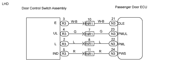
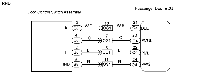
WIRING DIAGRAM
INSPECTION PROCEDURE
| 1.INSPECT DOOR CONTROL SWITCH ASSEMBLY |
Remove the door control switch.
Measure the resistance of the switch.
- Standard resistance:
Tester Connection
| Condition
| Specified Condition
|
2 - 3
| Lock
| Below 1 Ω
|
4 - 3
| Unlock
| Below 1 Ω
|
2 - 3
| Unlock
| 10 kΩ or higher
|
4 - 3
| Lock
| 10 kΩ or higher
|
| | REPLACE DOOR CONTROL SWITCH ASSEMBLY |
|
|
| 2.CHECK WIRE HARNESS (DOOR CONTROL SWITCH ASSEMBLY - PASSENGER DOOR ECU) |
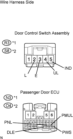
Disconnect the R3*1 or S8*2 switch connector.
Disconnect the N3*1 or O4*2 ECU connector.
Measure the resistance of the wire harness side connectors.
- Standard resistance:
LHDTester Connection
| Specified Condition
|
R3-3 (E) - N3-21 (DLE)
| Below 1 Ω
|
R3-4 (UL) - N3-23 (PMUL)
| Below 1 Ω
|
R3-2 (L) - N3-22 (PNL)
| Below 1 Ω
|
R3-5 (IND) - N3-24 (PWS)
| Below 1 Ω
|
- RHD:
Tester Connection
| Specified Condition
|
S8-3 (E) - O4-21 (DLE)
| Below 1 Ω
|
S8-4 (UL) - O4-23 (PMUL)
| Below 1 Ω
|
S8-2 (L) - O4-22 (PNL)
| Below 1 Ω
|
S8-5 (IND) - O4-24 (PWS)
| Below 1 Ω
|
- HINT:
- *1: LHD
- *2: RHD
| | REPAIR OR REPLACE HARNESS AND CONNECTOR |
|
|
| OK |
|
|
|
| REPLACE PASSENGER DOOR ECU |
|