Power Door Lock Control System -- Terminals Of Ecu |
| CHECK COWL SIDE JUNCTION BLOCK RH (MULTIPLEX NETWORK BODY ECU) |
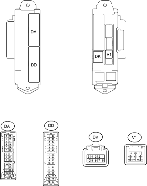
Disconnect the DA, DD and DK J/B connectors.
Disconnect the V1 ECU connector.
Measure the voltage and resistance of the wire harness side connectors.
If the result is not as specified, there may be a malfunction on the wire harness side.Symbols (Terminal No.) Wiring Color Terminal Description Condition Specified Condition BECU (DK-5) - GND2 (DA-5) G-R - W-B BECU power supply Always 10 to 14 V GND2 (DA-5) - Body ground W-B - Body ground Ground Always Below 1 Ω GND2 (DD-7) - Body ground W-B - Body ground Ground Always Below 1 Ω DCTY (V1-14) - Body ground R - Body ground Driver side door courtesy light switch signal Driver side door is closed Below 1 Ω DCTY (V1-14) - Body ground R - Body ground Driver side door courtesy light switch signal Driver side door is open 10 kΩ or higher
| CHECK DRIVER DOOR ECU |
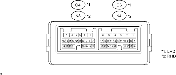
Disconnect the O3 and O4*1, or N3 and N4*2 ECU connectors.
Measure the voltage and resistance of the wire harness side connectors.
Symbols (Terminal No.) Wiring Color Terminal Description Condition Specified Condition CPUB (O3-4) - GND (O3-1)*1 LG - W-B Battery power supply Always 10 to 14 V BDR (O3-6) - GND (O3-1)*1 L - W-B Battery power supply Always 10 to 14 V SIG (O3-3) - GND (O3-1)*1 Y - W-B SIG power supply Engine switch on (IG) 10 to 14 V SIG (O3-3) - GND (O3-1)*1 Y - W-B SIG power supply Engine switch off Below 1 V GND (O3-1) - Body ground*1 W-B - Body ground Ground Always Below 1 Ω CPUB (N4-4) - GND (N4-1)*2 B - W-B Battery power supply Always 10 to 14 V BDR (N4-6) - GND (N4-1)*2 LR - W-B Battery power supply Always 10 to 14 V SIG (N4-3) - GND (N4-1)*2 O - W-B SIG power supply Engine switch on (IG) 10 to 14 V SIG (N4-3) - GND (N4-1)*2 O - W-B SIG power supply Engine switch off Below 1 V GND (N4-1) - Body ground*2 W-B - Body ground Ground Always Below 1 Ω DBSL (O4-3) - DBE (O4-4)*1, 3 GR - W-B Double lock position switch signal Double lock SET Below 1 Ω DBSL (O4-3) - DBE (O4-4)*1, 3 GR - W-B Double lock position switch signal Double lock UNSET 10 kΩ or higher DBSL (N3-3) - DBE (N3-4)*2, 3 GR - W-B Double lock position switch signal Double lock SET Below 1 Ω DBSL (N3-3) - DBE (N3-4)*2, 3 GR - W-B Double lock position switch signal Double lock UNSET 10 kΩ or higher - HINT:
- *1: LHD
- *2: RHD
- *3: w/ Double locking system
Reconnect the O3 and O4*1, or N3 and N4*2 ECU connectors.
Measure the voltage of the connectors.
Symbols (Terminal No.) Wiring Color Terminal Description Condition Specified Condition A- (O4-1) - GND (O3-1)*1 R - W-B Door lock motor LOCK drive output Door control switch (master switch or passenger side door control switch) or driver side door key cylinder UNLOCK 10 to 14 V A- (O4-1) - GND (O3-1)*1 R - W-B Door lock motor LOCK drive output Door control switch (master switch or passenger side door control switch) or driver side door key cylinder LOCK Below 1 V A+ (O4-2) - GND (O3-1)*1 G - W-B Door lock motor UNLOCK drive output Door control switch (master switch or passenger side door control switch) or driver side door key cylinder LOCK 10 to 14 V A+ (O4-2) - GND (O3-1)*1 G - W-B Door lock motor UNLOCK drive output Door control switch (master switch or passenger side door control switch) or driver side door key cylinder UNLOCK Below 1 V A- (N3-1) - GND (N4-1)*2 LG - W-B Door lock motor LOCK drive output Door control switch (master switch or passenger side door control switch) or driver side door key cylinder UNLOCK 10 to 14 V A- (N3-1) - GND (N4-1)*2 LG - W-B Door lock motor LOCK drive output Door control switch (master switch or passenger side door control switch) or driver side door key cylinder LOCK Below 1 V A+ (N3-2) - GND (N4-1)*2 G - W-B Door lock motor UNLOCK drive output Door control switch (master switch or passenger side door control switch) or driver side door key cylinder LOCK 10 to 14 V A+ (N3-2) - GND (N4-1)*2 G - W-B Door lock motor UNLOCK drive output Door control switch (master switch or passenger side door control switch) or driver side door key cylinder UNLOCK Below 1 V AI+ (O4-5) - GND (O3-1)*1, 3 G - W-B Double lock motor SET drive output Double lock SET 10 to 14 V AI+ (O4-5) - GND (O3-1)*1, 3 G - W-B Double lock motor SET drive output Double lock UNSET Below 1 V AI- (O4-6) - GND (O3-1)*1, 3 R - W-B Double lock motor SET drive output Double lock UNSET 10 to 14 V AI- (O4-6) - GND (O3-1)*1, 3 R - W-B Double lock motor SET drive output Double lock SET Below 1 V AI+ (N3-5) - GND (N4-1)*2, 3 G - W-B Double lock motor SET drive output Double lock SET 10 to 14 V AI+ (N3-5) - GND (N4-1)*2, 3 G - W-B Double lock motor SET drive output Double lock UNSET Below 1 V AI- (N3-6) - GND (N4-1)*2, 3 R - W-B Double lock motor SET drive output Double lock UNSET 10 to 14 V AI- (N3-6) - GND (N4-1)*2, 3 R - W-B Double lock motor SET drive output Double lock SET Below 1 V - HINT:
- *1: LHD
- *2: RHD
- *3: w/ Double locking system
| CHECK PASSENGER DOOR ECU |
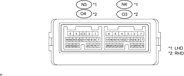
Disconnect the N3 and N4*1, or O3 and O4*2 ECU connectors.
Measure the voltage and resistance of the wire harness side connectors.
Symbols (Terminal No.) Wiring Color Terminal Description Condition Specified Condition CPUB (N4-4) - GND (N4-1)*1 B - W-B Battery power supply Always 10 to 14 V BDR (N4-6) - GND (N4-1)*1 LR - W-B Battery power supply Always 10 to 14 V SIG (N4-3) - GND (N4-1)*1 O - W-B SIG power supply Engine switch on (IG) 10 to 14 V SIG (N4-3) - GND (N4-1)*1 O - W-B SIG power supply Engine switch off Below 1 V GND (N4-1) - Body ground*1 W-B - Body ground Ground Always Below 1 Ω LSW (N3-14) - LSWE (N3-4)*1 G - LG Door lock position switch signal Passenger side door is locked Below 1 Ω LSW (N3-14) - LSWE (N3-4)*1 G - LG Door lock position switch signal Passenger side door is unlocked 10 kΩ or higher CPUB (O3-4) - GND (O3-1)*2 LG - W-B Battery power supply Always 10 to 14 V BDR (O3-6) - GND (O3-1)*2 L - W-B Battery power supply Always 10 to 14 V SIG (O3-3) - GND (O3-1)*2 Y - W-B SIG power supply Engine switch on (IG) 10 to 14 V SIG (O3-3) - GND (O3-1)*2 Y - W-B SIG power supply Engine switch off Below 1 V GND (O3-1) - Body ground*2 W-B - Body ground Ground Always Below 1 Ω LSW (O4-14) - LSWE (O4-4)*2 O - LG Door lock position switch signal Passenger side door is locked Below 1 Ω LSW (O4-14) - LSWE (O4-4)*2 O - LG Door lock position switch signal Passenger side door is unlocked 10 kΩ or higher DBSL (N3-3) - DBE (N3-4)*1, 3 GR - W-B Double lock position switch signal Double lock SET Below 1 Ω DBSL (N3-3) - DBE (N3-4)*1, 3 GR - W-B Double lock position switch signal Double lock UNSET 10 kΩ or higher DBSL (O4-3) - DBE (O4-4)*2, 3 GR - W-B Double lock position switch signal Double lock SET Below 1 Ω DBSL (O4-3) - DBE (O4-4)*2, 3 GR - W-B Double lock position switch signal Double lock UNSET 10 kΩ or higher - HINT:
- *1: LHD
- *2: RHD
- *3: w/ Double locking system
Reconnect the N3 and N4*1, or O3 and O4*2 ECU connectors.
Measure the voltage of the connectors.
Symbols (Terminal No.) Wiring Color Terminal Description Condition Specified Condition A- (N3-1) - GND (N4-1)*1 LG - W-B Door lock motor LOCK drive output Door control switch (master switch or passenger side door control switch) or driver side door key cylinder UNLOCK 10 to 14 V A- (N3-1) - GND (N4-1)*1 LG - W-B Door lock motor LOCK drive output Door control switch (master switch or passenger side door control switch) or driver side door key cylinder LOCK Below 1 V A+ (N3-2) - GND (N4-1)*1 G - W-B Door lock motor UNLOCK drive output Door control switch (master switch or passenger side door control switch) or driver side door key cylinder LOCK 10 to 14 V A+ (N3-2) - GND (N4-1)*1 G - W-B Door lock motor UNLOCK drive output Door control switch (master switch or passenger side door control switch) or driver side door key cylinder UNLOCK Below 1 V A- (O4-1) - GND (O3-1)*2 R - W-B Door lock motor LOCK drive output Door control switch (master switch or passenger side door control switch) or driver side door key cylinder UNLOCK 10 to 14 V A- (O4-1) - GND (O3-1)*2 R - W-B Door lock motor LOCK drive output Door control switch (master switch or passenger side door control switch) or driver side door key cylinder LOCK Below 1 V A+ (O4-2) - GND (O3-1)*2 G - W-B Door lock motor UNLOCK drive output Door control switch (master switch or passenger side door control switch) or driver side door key cylinder LOCK 10 to 14 V A+ (O4-2) - GND (O3-1)*2 G - W-B Door lock motor UNLOCK drive output Door control switch (master switch or passenger side door control switch) or driver side door key cylinder UNLOCK Below 1 V AI+ (N3-5) - GND (N4-1)*1, 3 G - W-B Double lock motor SET drive output Double lock SET 10 to 14 V AI+ (N3-5) - GND (N4-1)*1, 3 G - W-B Double lock motor SET drive output Double lock UNSET Below 1 V AI- (N3-6) - GND (N4-1)*1, 3 R - W-B Double lock motor SET drive output Double lock UNSET 10 to 14 V AI- (N3-6) - GND (N4-1)*1, 3 R - W-B Double lock motor SET drive output Double lock SET Below 1 V AI+ (O4-5) - GND (O3-1)*2, 3 G - W-B Double lock motor SET drive output Double lock SET 10 to 14 V AI+ (O4-5) - GND (O3-1)*2, 3 G - W-B Double lock motor SET drive output Double lock UNSET Below 1 V AI- (O4-6) - GND (O3-1)*2, 3 R - W-B Double lock motor SET drive output Double lock UNSET 10 to 14 V AI- (O4-6) - GND (O3-1)*2, 3 R - W-B Double lock motor SET drive output Double lock SET Below 1 V - HINT:
- *1: LHD
- *2: RHD
- *3: w/ Double locking system
| CHECK REAR DOOR ECU LH |
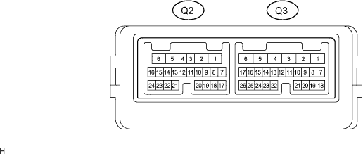
Disconnect the Q2 and Q3 ECU connectors.
Measure the voltage and resistance of the wire harness side connectors.
Symbols (Terminal No.) Wiring Color Terminal Description Condition Specified Condition CPUB (Q2-4) - GND (Q2-1) BR - W-B Battery power supply Always 10 to 14 V BDR (Q2-6) - GND (Q2-1) L - W-B Battery power supply Always 10 to 14 V SIG (Q2-3) - GND (Q2-1) G - W-B SIG power supply Engine switch on (IG) 10 to 14 V SIG (Q2-3) - GND (Q2-1) G - W-B SIG power supply Engine switch off Below 1 V GND (Q2-1) - Body ground W-B - Body ground Ground Always Below 1 Ω LSW (Q3-14) - LSWE (Q3-13) LG - W-B Rear door side LH door lock position switch input Rear door side LH door is UNLOCK Below 1 Ω LSW (Q3-14) - LSWE (Q3-13) LG - W-B Rear door side LH door lock position switch input Rear door side LH door is LOCK 10 kΩ or higher DBSL (Q3-3) - DBE (Q3-4)* GR - W-B Double lock position switch signal Double lock SET Below 1 Ω DBSL (Q3-3) - DBE (Q3-4)* GR - W-B Double lock position switch signal Double lock UNSET 10 kΩ or higher - HINT:
- *: w/ Double locking system
Reconnect the Q2 and Q3 ECU connectors.
Measure the voltage of the connectors.
Symbols (Terminal No.) Wiring Color Terminal Description Condition Specified Condition A- (Q3-1) - GND (Q2-1) G - W-B Door lock motor LOCK drive output Door control switch (master switch or passenger side door control switch) or driver side door key cylinder UNLOCK 10 to 14 V A- (Q3-1) - GND (Q2-1) G - W-B Door lock motor LOCK drive output Door control switch (master switch or passenger side door control switch) or driver side door key cylinder LOCK Below 1 V A+ (Q3-2) - GND (Q2-1) O - W-B Door lock motor UNLOCK drive output Door control switch (master switch or passenger side door control switch) or driver side door key cylinder LOCK 10 to 14 V A+ (Q3-2) - GND (Q2-1) O - W-B Door lock motor UNLOCK drive output Door control switch (master switch or passenger side door control switch) or driver side door key cylinder UNLOCK Below 1 V AI+ (Q3-5) - GND (Q2-1)* G - W-B Double lock motor SET drive output Double lock SET 10 to 14 V AI+ (Q3-5) - GND (Q2-1)* G - W-B Double lock motor SET drive output Double lock UNSET Below 1 V AI- (Q3-6) - GND (Q2-1)* R - W-B Double lock motor SET drive output Double lock UNSET 10 to 14 V AI- (Q3-6) - GND (Q2-1)* R - W-B Double lock motor SET drive output Double lock SET Below 1 V - HINT:
- *: w/ Double locking system
| CHECK REAR DOOR ECU RH |
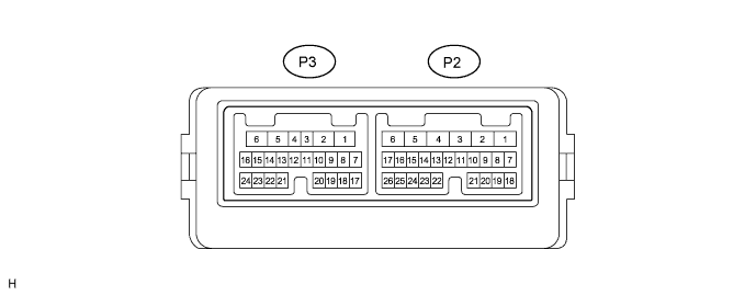
Disconnect the P2 and P3 ECU connectors.
Measure the voltage and resistance of the wire harness side connectors.
Symbols (Terminal No.) Wiring Color Terminal Description Condition Specified Condition CPUB (P3-4) - GND (P3-1) G - W-B Battery power supply Always 10 to 14 V BDR (P3-6) - GND (P3-1) L - W-B Battery power supply Always 10 to 14 V SIG (P3-3) - GND (P3-1) L - W-B SIG power supply Engine switch on (IG) 10 to 14 V SIG (P3-3) - GND (P3-1) L - W-B SIG power supply Engine switch off Below 1 V GND (P3-1) - Body ground W-B - Body ground Ground Always Below 1 Ω LSW (P2-14) - LSWE (P2-13) LG - W-B Rear door side RH door lock position switch input Rear door side RH door UNLOCK Below 1 Ω LSW (P2-14) - LSWE (P2-13) LG - W-B Rear door side RH door lock position switch input Rear door side RH door UNLOCK 10 kΩ or higher DBSL (P2-3) - DBE (P2-4)* GR - W-B Double lock position switch signal Double lock SET Below 1 Ω DBSL (P2-3) - DBE (P2-4)* GR - W-B Double lock position switch signal Double lock UNSET 10 kΩ or higher - HINT:
- *: w/ Double locking system
Reconnect the P2 and P3 ECU connectors.
Measure the voltage of the connectors.
Symbols (Terminal No.) Wiring Color Terminal Description Condition Specified Condition A- (P2-1) - GND (P3-1) G - W-B Door lock motor LOCK drive output Door control switch (master switch or passenger side door control switch) or driver side door key cylinder UNLOCK 10 to 14 V A- (P2-1) - GND (P3-1) G - W-B Door lock motor LOCK drive output Door control switch (master switch or passenger side door control switch) or driver side door key cylinder LOCK Below 1 V A+ (P2-2) - GND (P3-1) O - W-B Door lock motor UNLOCK drive output Door control switch (master switch or passenger side door control switch) or driver side door key cylinder LOCK 10 to 14 V A+ (P2-2) - GND (P3-1) O - W-B Door lock motor UNLOCK drive output Door control switch (master switch or passenger side door control switch) or driver side door key cylinder UNLOCK Below 1 V AI+ (P2-5) - GND (P3-1)* G - W-B Double lock motor SET drive output Double lock SET 10 to 14 V AI+ (P2-5) - GND (P3-1)* G - W-B Double lock motor SET drive output Double lock UNSET Below 1 V AI- (P2-6) - GND (P3-1)* R - W-B Double lock motor SET drive output Double lock UNSET 10 to 14 V AI- (P2-6) - GND (P3-1)* R - W-B Double lock motor SET drive output Double lock SET Below 1 V - HINT:
- *: w/ Double locking system
| CHECK MULTIPLEX NETWORK MASTER SWITCH ASSEMBLY |
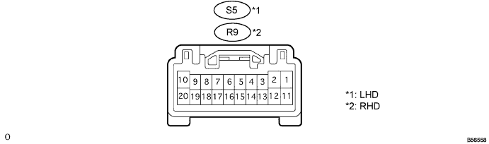
Disconnect the S5*1 or R9*2 switch connector.
Measure the voltage and resistance of the wire harness side connector.
Symbols (Terminal No.) Wiring Color Terminal Description Condition Specified Condition CPUB (S5-9) - E (S5-2)*1 G - W-B Battery power supply Always 10 to 14 V BDR1 (S5-10) - E (S5-2)*1 Y - W-B Battery power supply Always 10 to 14 V SIG (S5-20) - E (S5-2)*1 V - W-B SIG power supply Engine switch on (IG) 10 to 14 V SIG (S5-20) - E (S5-2)*1 V - W-B SIG power supply Engine switch off Below 1 V E (S5-20) - Body ground*1 W-B - Body ground Ground Always Below 1 Ω KL (S5-4) - E (S5-2)*1 LG - W-B Door key-linked door lock input Using key, operate driver door lock cylinder LOCK Below 1 Ω KL (S5-4) - E (S5-2)*1 LG - W-B Door key-linked door lock input Using key, operate driver door lock cylinder UNLOCK 10 kΩ or higher KUL (S5-14) - E (S5-2)*1 P - W-B Door key-linked door unlock input Using key, operate driver door lock cylinder LOCK Below 1 Ω KUL (S5-14) - E (S5-2)*1 P - W-B Door key-linked door unlock input Using key, operate driver door lock cylinder UNLOCK 10 kΩ or higher LSW (S5-16) - E (S5-2)*1 Y - W-B Driver side door lock position switch input Driver side door is unlocked Below 1 Ω LSW (S5-16) - E (S5-2)*1 Y - W-B Driver side door lock position switch input Driver side door is locked 10 kΩ or higher CPUB (R9-9) - E (R9-2)*2 G - W-B Battery power supply Always 10 to 14 V BDR1 (R9-10) - E (R9-2)*2 Y - W-B Battery power supply Always 10 to 14 V SIG (R9-20) - E (R9-2)*2 V - W-B SIG power supply Engine switch on (IG) 10 to 14 V SIG (R9-20) - E (R9-2)*2 V - W-B SIG power supply Engine switch off Below 1 V E (R9-20) - Body ground*2 W-B - Body ground Ground Always Below 1 Ω KL (R9-4) - E (R9-2)*2 LG - W-B Door key-linked door lock input Using key, operate driver door lock cylinder LOCK Below 1 Ω KL (R9-4) - E (R9-2)*2 LG - W-B Door key-linked door lock input Using key, operate driver door lock cylinder UNLOCK 10 kΩ or higher KUL (R9-14) - E (R9-2)*2 P - W-B Door key-linked door unlock input Using key, operate driver door lock cylinder LOCK Below 1 Ω KUL (R9-14) - E (R9-2)*2 P - W-B Door key-linked door unlock input Using key, operate driver door lock cylinder UNLOCK 10 kΩ or higher LSW (R9-16) - E (R9-2)*2 Y - W-B Driver side door lock position switch input Driver side door is unlocked Below 1 Ω LSW (R9-16) - E (R9-2)*2 Y - W-B Driver side door lock position switch input Driver side door is locked 10 kΩ or higher - HINT:
- *1: LHD
- *2: RHD