Wiper And Washer System Front Wiper Motor Circuit
DESCRIPTION
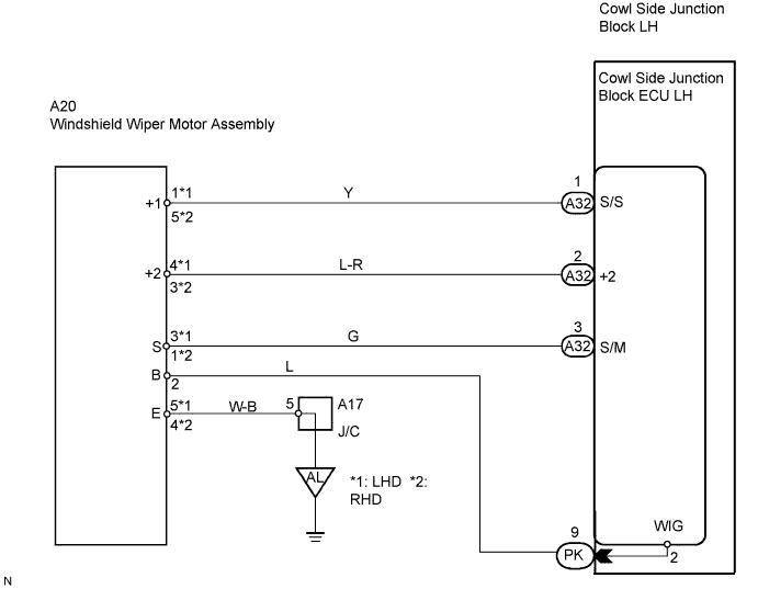
WIRING DIAGRAM
INSPECTION PROCEDURE
PERFORM ACTIVE TEST BY INTELLIGENT TESTER
INSPECT WINDSHIELD WIPER MOTOR ASSEMBLY
CHECK WIRE HARNESS (WINDSHIELD WIPER MOTOR ASSEMBLY - COWL SIDE JUNCTION BLOCK LH)
WIPER AND WASHER SYSTEM - Front Wiper Motor Circuit |
DESCRIPTION
The cowl side junction block ECU LH controls the wiper motor.
WIRING DIAGRAM
INSPECTION PROCEDURE
| 1.PERFORM ACTIVE TEST BY INTELLIGENT TESTER |
Connect the intelligent tester to the DLC3.
Turn the engine switch on (IG) and turn the intelligent tester's main switch ON.
Select the item below in the Active Test and then check that the front wiper motor operates.
Cowl side junction block ECU LH:Item
| Test Details
| Diagnostic Note
|
WIPER MOT (HI)
| Front wiper motor HI operation ON / OFF
| -
|
WIPER MOT (LO)
| Front wiper motor LO operation ON / OFF
| -
|
- OK:
- Front wiper motor operates.
| OK |
|
|
|
| PROCEED TO NEXT CIRCUIT INSPECTION SHOWN IN PROBLEM SYMPTOMS TABLE |
|
| 2.INSPECT WINDSHIELD WIPER MOTOR ASSEMBLY |
Remove the windshield wiper motor (Click here).
Check the LO operation.
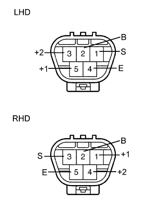
LHD:
Connect the positive (+) battery lead to terminal 5 (+1) of the connector, and the negative (-) battery lead to terminal 4 (E), and check that the motor operates at low speed.
Connect the positive (+) battery lead to terminal 3 (+2) of the connector, and the negative (-) battery lead to terminal 1 (S), and check that the motor operates at high speed.
RHD:
Connect the positive (+) battery lead to terminal 1 (+1) of the connector, and the negative (-) battery lead to terminal 5(E), and check that the motor operates at low speed.
Connect the positive (+) battery lead to terminal 4 (+2) of the connector, and the negative (-) battery lead to terminal 3 (S), and check that the motor operates at high speed.
| | REPLACE WIPER MOTOR ASSEMBLY |
|
|
| 3.CHECK WIRE HARNESS (WINDSHIELD WIPER MOTOR ASSEMBLY - COWL SIDE JUNCTION BLOCK LH) |
Disconnect the A20 wiper motor connector.
Disconnect the A32 ECU LH connector.
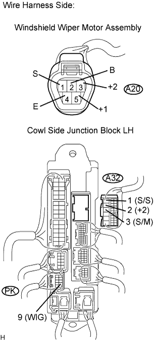
Measure the resistance of the wire harness side connectors.
- HINT:
- *1: LHD
- *2: RHD
- Standard resistance:
Tester Connection
| Condition
| Specified Condition
|
PK-9 (WIG) - A20-2 (B)
| Always
| Below 1 Ω
|
A32-1 (S/S) - A20-1*1 (+1)
| Always
| Below 1 Ω
|
A32-1 (S/S) - A20-5*2 (+1)
|
A32-2 (+2) - A20-4*1 (+2)
| Always
| Below 1 Ω
|
A32-2 (+2) - A20-3*2 (+2)
|
A32-3 (S/M) - A20-3*1 (S)
| Always
| Below 1 Ω
|
A32-3 (S/M) - A20-1*2 (S)
|
A20-3*1 (S) - Body ground
| Always
| 10 kΩ or higher
|
A20-1*2 (S) - Body ground
|
A20-2 (B) - Body ground
| Always
| 10 kΩ or higher
|
A20-4*1 (+2) - Body ground
| Always
| 10 kΩ or higher
|
A20-3*2 (+2) - Body ground
|
A20-5*1 (E) - Body ground
| Always
| 10 kΩ or higher
|
A20-4*2 (E) - Body ground
|
A20-1*1 (+1) - Body ground
| Always
| 10 kΩ or higher
|
A20-5*2 (+1) - Body ground
|
| | REPAIR OR REPLACE HARNESS AND CONNECTOR |
|
|
| OK |
|
|
|
| PROCEED TO NEXT CIRCUIT INSPECTION SHOWN IN PROBLEM SYMPTOMS TABLE |
|