Lighting. Lexus Gs430, Gs300. Uzs190 Grs190
DESCRIPTION
WIRING DIAGRAM
INSPECTION PROCEDURE
CHECK OPERATION OF FOOT LIGHT
PERFORM ACTIVE TEST BY INTELLIGENT TESTER
INSPECT FUSE (DOME, D/C CUT)
REPLACE FOOT LIGHT (LH)
CHECK WIRE HARNESS (FOOT LIGHT (LH) - BATTERY)
CHECK WIRE HARNESS (FOOT LIGHT (LH) - MULTIPLEX NETWORK BODY ECU)
REPLACE FOOT LIGHT (RH)
CHECK WIRE HARNESS (FOOT LIGHT (RH) - BATTERY)
CHECK WIRE HARNESS (FOOT LIGHT (RH) - MULTIPLEX NETWORK BODY ECU)
REPLACE FOOT LIGHT (REAR LH)
CHECK WIRE HARNESS (FOOT LIGHT (REAR LH) - BATTERY)
CHECK WIRE HARNESS (FOOT LIGHT (REAR LH) - MULTIPLEX NETWORK BODY ECU)
REPLACE FOOT LIGHT (REAR RH)
CHECK WIRE HARNESS (FOOT LIGHT (REAR RH) - BATTERY)
CHECK WIRE HARNESS (FOOT LIGHT (REAR RH) - MULTIPLEX NETWORK BODY ECU)
LIGHTING SYSTEM - Step Illumination Circuit |
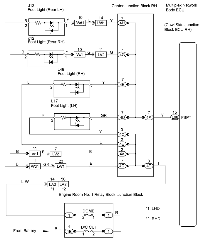
DESCRIPTION
The multiplex network body ECU receives information regarding the door lock position switch and engine switch, and turns on each step light. It also receives shift information and controls the illumination.
WIRING DIAGRAM
INSPECTION PROCEDURE
| 1.CHECK OPERATION OF FOOT LIGHT |
When a door is opened, check that the appropriate light illuminates.
- Result:
Result
| Proceed to
|
All lights do not illuminate
| A
|
Foot light (LH) does not illuminate
| B
|
Foot light (RH) does not illuminate
| C
|
Foot light (Rear LH) does not illuminate
| D
|
Foot light (Rear RH) does not illuminate
| E
|
| 2.PERFORM ACTIVE TEST BY INTELLIGENT TESTER |
Select the Active Test, use the intelligent tester to generate a control command, and then check that the step light illuminates.
- Multiplex network body ECU :
Item
| Test Details
| Diagnostic Note
|
Step Light Operation
| Step light operation ON / OFF
| -
|
- OK:
- Step light illuminates.
| OK |
|
|
|
| PROCEED TO NEXT CIRCUIT INSPECTION SHOWN IN PROBLEM SYMPTOMS TABLE |
|
| 3.INSPECT FUSE (DOME, D/C CUT) |
Remove the DOME fuse from the engine room No. 1 relay block.
Remove the D/C CUT fuse from the engine room No. 1 relay block.
Measure the resistance of the fuses.
- Standard resistance:
- Below 1 Ω
| OK |
|
|
|
| PROCEED TO NEXT CIRCUIT INSPECTION SHOWN IN PROBLEM SYMPTOMS TABLE |
|
| 4.REPLACE FOOT LIGHT (LH) |
Temporarily replace the foot light (LH) with a new or normally functioning one.
Check that the foot light illuminates.
- OK:
- Foot light illuminates.
| 5.CHECK WIRE HARNESS (FOOT LIGHT (LH) - BATTERY) |
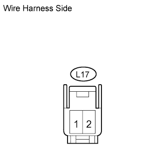
Disconnect the L17 light connector.
Measure the voltage of the wire harness side connector.
- Standard voltage:
Tester Connection
| Specified Condition
|
L17-2 - Body ground
| 10 to 14 V
|
| | REPAIR OR REPLACE HARNESS AND CONNECTOR |
|
|
| 6.CHECK WIRE HARNESS (FOOT LIGHT (LH) - MULTIPLEX NETWORK BODY ECU) |
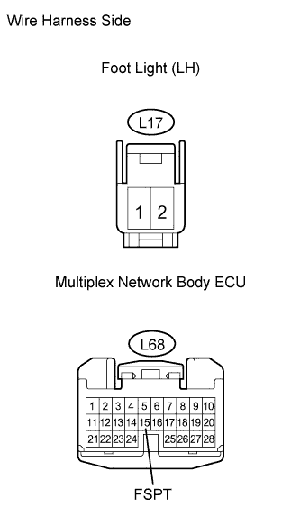
Disconnect the L17 light connector.
Disconnect the L68 ECU connector.
Measure the resistance of the wire harness side connector.
- Standard resistance:
Tester Connection
| Specified Condition
|
L17-1 - L68-15 (FSPT)
| Below 1 Ω
|
L17-1 or L68-15 (FSPT) - Body ground
| 10 kΩ or higher
|
| | REPAIR OR REPLACE HARNESS AND CONNECTOR |
|
|
| OK |
|
|
|
| PROCEED TO NEXT CIRCUIT INSPECTION SHOWN IN PROBLEM SYMPTOMS TABLE |
|
| 7.REPLACE FOOT LIGHT (RH) |
Temporarily replace the foot light (RH) with a new or normally functioning one.
Check that the foot light illuminates.
- OK:
- Foot light illuminates.
| 8.CHECK WIRE HARNESS (FOOT LIGHT (RH) - BATTERY) |
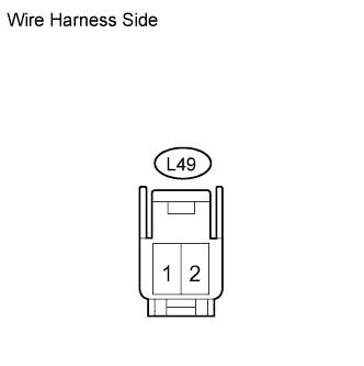
Disconnect the L49 light connector.
Measure the voltage of the wire harness side connector.
- Standard voltage:
Tester Connection
| Specified Condition
|
L49-2 - Body ground
| 10 to 14 V
|
| | REPAIR OR REPLACE HARNESS AND CONNECTOR |
|
|
| 9.CHECK WIRE HARNESS (FOOT LIGHT (RH) - MULTIPLEX NETWORK BODY ECU) |
Disconnect the L49 light connector.
Disconnect the L68 ECU connector.
Measure the resistance of the wire harness side connectors.
- Standard resistance:
Tester Connection
| Specified Condition
|
L49-1 - L68-15 (FSPT)
| Below 1 Ω
|
L49-1 or L68-15 (FSPT) - Body ground
| 10 kΩ or higher
|
| | REPAIR OR REPLACE HARNESS AND CONNECTOR |
|
|
| OK |
|
|
|
| PROCEED TO NEXT CIRCUIT INSPECTION SHOWN IN PROBLEM SYMPTOMS TABLE |
|
| 10.REPLACE FOOT LIGHT (REAR LH) |
Temporarily replace the foot light (rear LH) with a new or normally functioning one.
Check that the foot light illuminates.
- OK:
- Foot light illuminates.
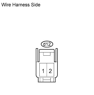
| 11.CHECK WIRE HARNESS (FOOT LIGHT (REAR LH) - BATTERY) |
Disconnect the d12 light connector.
Measure the voltage of the wire harness side connector.
- Standard voltage:
Tester Connection
| Specified Condition
|
d12-2 - Body ground
| 10 to 14 V
|
| | REPAIR OR REPLACE HARNESS AND CONNECTOR |
|
|
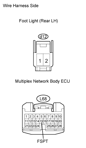
| 12.CHECK WIRE HARNESS (FOOT LIGHT (REAR LH) - MULTIPLEX NETWORK BODY ECU) |
Disconnect the d12 light connector.
Disconnect the L68 ECU connector.
Measure the resistance of the wire harness side connectors.
- Standard resistance:
Tester Connection
| Specified Condition
|
d12-1 - L68-15 (FSPT)
| Below 1 Ω
|
d12-1 or L68-15 (FSPT) - Body ground
| 10 kΩ or higher
|
| | REPAIR OR REPLACE HARNESS AND CONNECTOR |
|
|
| OK |
|
|
|
| PROCEED TO NEXT CIRCUIT INSPECTION SHOWN IN PROBLEM SYMPTOMS TABLE |
|
| 13.REPLACE FOOT LIGHT (REAR RH) |
Temporarily replace the foot light (rear RH) with a new or normally functioning one.
Check that the foot light illuminates.
- OK:
- Foot light illuminates.
| 14.CHECK WIRE HARNESS (FOOT LIGHT (REAR RH) - BATTERY) |
Disconnect the c12 light connector.
Measure the voltage of the wire harness side connector.
- Standard voltage:
Tester Connection
| Specified Condition
|
c12-2 - Body ground
| 10 to 14 V
|
| | REPAIR OR REPLACE HARNESS AND CONNECTOR |
|
|
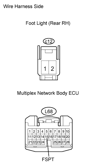
| 15.CHECK WIRE HARNESS (FOOT LIGHT (REAR RH) - MULTIPLEX NETWORK BODY ECU) |
Disconnect the c12 light connector.
Disconnect the L68 ECU connector.
Measure the resistance of the wire harness side connectors.
- Standard resistance:
Tester Connection
| Specified Condition
|
c12-1 - L68-15 (FSPT)
| Below 1 Ω
|
c12-1 or L68-15 (FSPT) - Body ground
| 10 kΩ or higher
|
| | REPAIR OR REPLACE HARNESS AND CONNECTOR |
|
|
| OK |
|
|
|
| PROCEED TO NEXT CIRCUIT INSPECTION SHOWN IN PROBLEM SYMPTOMS TABLE |
|