Lighting. Lexus Gs430, Gs300. Uzs190 Grs190
DESCRIPTION
WIRING DIAGRAM
INSPECTION PROCEDURE
READ VALUE OF INTELLIGENT TESTER
INSPECT FUSE (STOP SW)
INSPECT STOP LIGHT SWITCH
CHECK WIRE HARNESS (NO. 1 JUNCTON BLOCK - BATTERY)
PERFORM ACTIVE TEST BY INTELLIGENT TESTER
INSPECT FUSE (STOP LP L, STOP LP R)
CHECK WIRE HARNESS (NO. 1 JUNCTION BLOCK - BATTERY)
CHECK WIRE HARNESS (NO. 1 JUNCTION BLOCK - LIGHT (STOP LH OR STOP RH) - BODY GROUND)
REPLACE REAR COMBINATION LIGHT (STOP LH OR STOP RH)
REPLACE NOISE FILTER
REPLACE CENTER STOP LIGHT
CHECK WIRE HARNESS (NO. 1 JUNCTION BLOCK - NOISE FILTER)
CHECK WIRE HARNESS (NOISE FILTER - CENTER STOP LIGHT)
CHECK WIRE HARNESS (CENTER STOP LIGHT - BODY GROUND)
LIGHTING SYSTEM - Stop Light Circuit |
DESCRIPTION
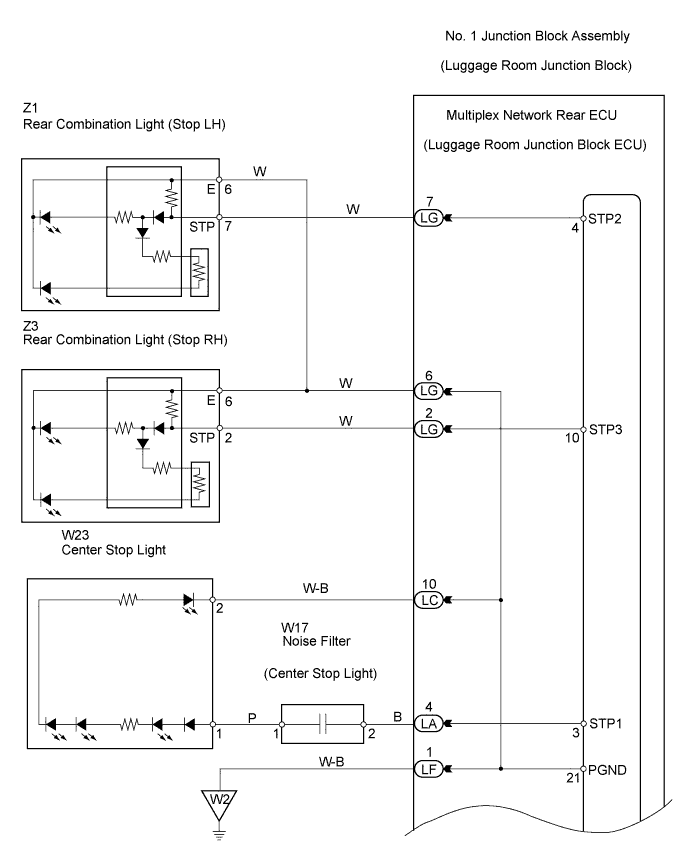
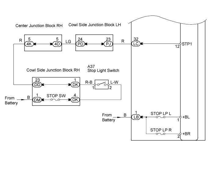
The multiplex network rear ECU receives stop light switch information from the stop light switch and turns on the stop light.
WIRING DIAGRAM
INSPECTION PROCEDURE
| 1.READ VALUE OF INTELLIGENT TESTER |
Select the Data List, use the intelligent tester to generate a control command, and then check that the stop light illuminates.
- Multiplex network rear ECU:
Item
| Measurement Item / Display (Range)
| Normal Condition
| Diagnostic Note
|
Stop Light Switch
| Stop light switch / ON or OFF
| ON: Brake pedal depressed
OFF: Brake pedal released
| -
|
- OK:
- Each light illuminates.
Remove the STOP SW fuse from the cowl side junction block RH.
Measure the resistance of the fuse.
- Standard resistance:
- Below 1 Ω
| 3.INSPECT STOP LIGHT SWITCH |
Inspection (Click here)- OK:
- Stop light switch is normal.
| | REPLACE STOP LIGHT SWITCH |
|
|
| 4.CHECK WIRE HARNESS (NO. 1 JUNCTON BLOCK - BATTERY) |
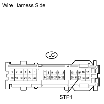
Disconnect the LC junction block connector.
Measure the voltage of the wire harness side connector.
- Standard voltage:
Tester Connection
| Condition
| Specified Condition
|
LC-32 (STP1) - Body ground
| Brake pedal is depressed
| 10 to 14 V
|
| | REPAIR OR REPLACE HARNESS AND CONNECTOR |
|
|
| 5.PERFORM ACTIVE TEST BY INTELLIGENT TESTER |
Select the Active Test, use the intelligent tester to generate a control command, and then check that the stop light illuminates.
- Multiplex network rear ECU:
Item
| Test Details
| Diagnostic Note
|
Stop Light
| Stop light ON / OFF
| -
|
High mount stop light
| High mount stop light ON / OFF
| -
|
- Result:
Result
| Proceed to
|
OK
| A
|
Both do not illuminate
| B
|
Combination light (stop LH or stop RH) does not illuminate
| C
|
High mount stop light does not illuminate
| D
|
| A |
|
|
|
| PROCEED TO NEXT CIRCUIT INSPECTION SHOWN IN PROBLEM SYMPTOMS TABLE |
|
| 6.INSPECT FUSE (STOP LP L, STOP LP R) |
Remove the STOP LP L fuse from the No. 1 junction block.
Remove the STOP LP R fuse from the No. 1 junction block.
Measure the resistance of the fuses.
- Standard resistance:
- Below 1 Ω
| 7.CHECK WIRE HARNESS (NO. 1 JUNCTION BLOCK - BATTERY) |
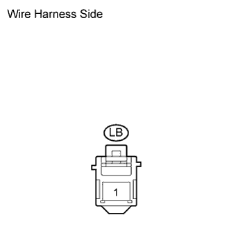
Disconnect the LB junction block connector.
Measure the voltage of the wire harness side connector.
- Standard voltage:
Tester Connection
| Specified Condition
|
LB-1 - Body ground
| 10 to 14 V
|
| | REPAIR OR REPLACE HARNESS AND CONNECTOR |
|
|
| OK |
|
|
|
| PROCEED TO NEXT CIRCUIT INSPECTION SHOWN IN PROBLEM SYMPTOMS TABLE |
|
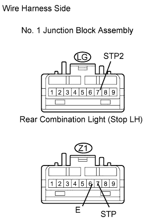
| 8.CHECK WIRE HARNESS (NO. 1 JUNCTION BLOCK - LIGHT (STOP LH OR STOP RH) - BODY GROUND) |
Check the wire harness between the rear combination light (stop LH) and No. 1 junction block, and the rear combination light (stop LH) and body ground.
Disconnect the LG junction block connector.
Disconnect the Z1 light connector.
Measure the resistance of the wire harness side connectors.
- Standard resistance:
Tester Connection
| Specified Condition
|
LG-7 (STP2) - Z1-7 (STP)
| Below 1 Ω
|
LG-7 (STP2) or Z1-7 (STP) - Body ground
| 10 kΩ or higher
|
Connect the LG junction block connector.
Measure the resistance of the wire harness side connector.
- Standard resistance:
Tester Connection
| Specified Condition
|
Z1-6 (E) - Body ground
| Below 1 Ω
|
Check the wire harness between the rear combination light (stop RH) and No. 1 junction block, and the rear combination light (stop RH) and body ground.
Disconnect the LG junction block connector.
Disconnect the Z3 light connector.
Measure the resistance of the wire harness side connectors.
- Standard resistance:
Tester Connection
| Specified Condition
|
LG-2 (STP3) - Z3-2 (STP)
| Below 1 Ω
|
LG-2 (STP3) or Z3-2 (STP) - Body ground
| 10 kΩ or higher
|
Connect the LG junction block connector.
Measure the resistance of the wire harness side connector.
- Standard resistance:
Tester Connection
| Specified Condition
|
Z3-6 (E) - Body ground
| Below 1 Ω
|
| | REPAIR OR REPLACE HARNESS AND CONNECTOR |
|
|
| 9.REPLACE REAR COMBINATION LIGHT (STOP LH OR STOP RH) |
Temporarily replace the rear combination light (stop LH or stop RH) with a new or normally functioning one.
Check that the light illuminates.
- OK:
- Light illuminates.
| NG |
|
|
|
| PROCEED TO NEXT CIRCUIT INSPECTION SHOWN IN PROBLEM SYMPTOMS TABLE |
|
Temporarily replace the noise filter with a new or normally functioning one.
Check that the light illuminates.
- OK:
- Light illuminates.
| 11.REPLACE CENTER STOP LIGHT |
Temporarily replace the center stop light with a new or normally functioning one.
Check that the light illuminates.
- OK:
- Light illuminates.
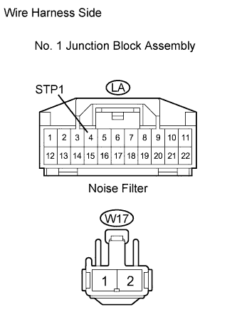
| 12.CHECK WIRE HARNESS (NO. 1 JUNCTION BLOCK - NOISE FILTER) |
Disconnect the LA junction block connector.
Disconnect the W17 noise filter connector.
Measure the resistance of the wire harness side connectors.
- Standard resistance:
Tester Connection
| Specified Condition
|
LA-4 (STP1) - W17-2
| Below 1 Ω
|
LA-4 (STP1) or W17-2 - Body ground
| 10 kΩ or higher
|
| | REPAIR OR REPLACE HARNESS AND CONNECTOR |
|
|
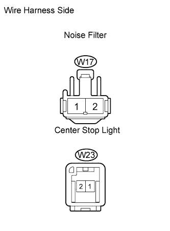
| 13.CHECK WIRE HARNESS (NOISE FILTER - CENTER STOP LIGHT) |
Disconnect the W17 noise filter connector.
Disconnect the W23 light connector.
Measure the resistance of the wire harness side connectors.
- Standard resistance:
Tester Connection
| Specified Condition
|
W17-1 - W23-1
| Below 1 Ω
|
W17-1 or W23-1 - Body ground
| 10 kΩ or higher
|
| | REPAIR OR REPLACE HARNESS AND CONNECTOR |
|
|
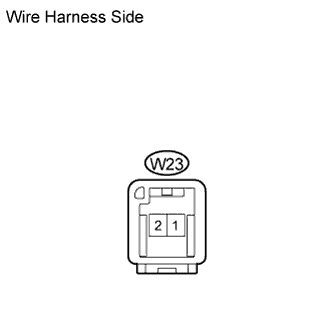
| 14.CHECK WIRE HARNESS (CENTER STOP LIGHT - BODY GROUND) |
Disconnect the W23 light connector.
Measure the resistance of the wire harness side connector.
- Standard resistance:
Tester Connection
| Specified Condition
|
W23-2 - Body ground
| Below 1 Ω
|
| | REPAIR OR REPLACE HARNESS AND CONNECTOR |
|
|
| OK |
|
|
|
| PROCEED TO NEXT CIRCUIT INSPECTION SHOWN IN PROBLEM SYMPTOMS TABLE |
|