Cruise Control System Cruise Control Switch Circuit
DESCRIPTION
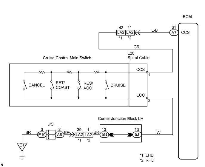
WIRING DIAGRAM
INSPECTION PROCEDURE
READ VALUE OF INTELLIGENT TESTER
INSPECT CRUISE CONTROL MAIN SWITCH
INSPECT SPIRAL CABLE
CHECK WIRE HARNESS (SPIRAL CABLE - ECM AND BODY GROUND)
CRUISE CONTROL SYSTEM - Cruise Control Switch Circuit |
DESCRIPTION
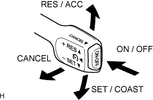
The cruise control main switch operates 7 functions: SET, COAST, TAP-DOWN, RESUME, ACCEL, TAP-UP, and CANCEL. The SET, TAP-DOWN and COAST functions, and the RESUME, TAP-UP and ACCEL functions are operated with the same switch. The cruise control main switch is an automatic return type switch which turns on only while operating it in each arrow direction and turns off after releasing it. The internal contact point of the cruise control main switch is turned on with the switch operation. Then the ECM reads the resistance value that has been changed by the switch operation to control SET, COAST, RESUME, ACCEL and CANCEL.
WIRING DIAGRAM
INSPECTION PROCEDURE
| 1.READ VALUE OF INTELLIGENT TESTER |
Connect the intelligent tester to the DLC3.
Turn the engine switch on (IG) and turn the intelligent tester main switch ON.
Check the Data List for proper functioning of the cruise control main switch.
ECM (Cruise control):Item
| Measurement Item / Display (Range)
| Normal Condition
| Diagnostic Note
|
Main SW (Main)
| Main switch signal (Main CPU) / ON or OFF
| ON: Main switch ON (Pushed on)
OFF: Main switch OFF (Pushed off)
| -
|
Cancel SW
| Cancel switch signal / ON or OFF
| ON: Cancel switch ON
OFF: Cancel switch OFF
| -
|
SET/COAST SW
| SET / COAST switch signal / ON or OFF
| ON: SET / COAST switch ON
OFF: SET / COAST switch OFF
| -
|
RES/ACC SW
| RES / ACC switch signal / ON or OFF
| ON: RES / ACC switch ON
OFF: RES / ACC switch OFF
| -
|
- OK:
- When cruise control main switch operation is performed, the results will be same as above.
Result:Result
| Proceed to
|
OK
| A
|
NG (All items are defective)
| B
|
NG (1 to 3 items are defective)
| C
|
| | PROCEED TO NEXT CIRCUIT INSPECTION SHOWN IN PROBLEM SYMPTOMS TABLE |
|
|
| | REPLACE CRUISE CONTROL MAIN SWITCH |
|
|
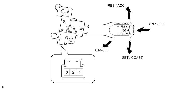
| 2.INSPECT CRUISE CONTROL MAIN SWITCH |
Disconnect the cruise control main switch connector.
Measure the resistance according to the value(s) in the table below.
- Standard resistance:
Tester Connection
| Switch Condition
| Specified Condition
|
1 - 3
| Neutral
| 10 kΩ or higher
|
1 - 3
| RES / ACC
| 235 to 245 Ω
|
1 - 3
| SET / COAST
| 620 to 640 Ω
|
1 - 3
| CANCEL
| 1,510 to 1,570 Ω
|
1 - 3
| Main Switch OFF
| 10 kΩ or higher
|
1 - 3
| Main Switch ON
| Below 1 Ω
|
| | REPLACE CRUISE CONTROL MAIN SWITCH |
|
|
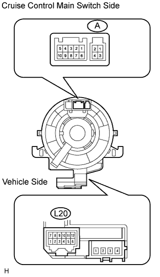
Disconnect the spiral cable connectors.
Measure the resistance of the connectors.
- Standard resistance:
Tester Connection
| Specified Condition
|
A-3 - L20-1
| Below 1 Ω
|
A-4 - L20-2
| Below 1 Ω
|
| 4.CHECK WIRE HARNESS (SPIRAL CABLE - ECM AND BODY GROUND) |
Disconnect the A7 ECM connector.
Measure the resistance of the wire harness side connectors.
- Standard resistance:
Tester Connection
| Condition
| Specified Condition
|
L20-1 - A7-31 (CCS)
| Always
| Below 1 Ω
|
A7-31 (CCS) - Body ground
| Always
| 10 kΩ or higher
|
L20-2 - Body ground
| Always
| Below 1 Ω
|
| | REPAIR OR REPLACE HARNESS AND CONNECTOR |
|
|
| OK |
|
|
|
| PROCEED TO NEXT CIRCUIT INSPECTION SHOWN IN PROBLEM SYMPTOMS TABLE |
|