Dtc B1451/51 Compressor Solenoid Circuit
DESCRIPTION
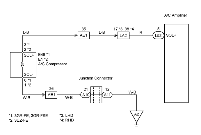
WIRING DIAGRAM
INSPECTION PROCEDURE
READ VALUE OF INTELLIGENT TESTER
INSPECT A/C COMPRESSOR
CHECK WIRE HARNESS (A/C COMPRESSOR - BODY GROUND)
CHECK WIRE HARNESS (A/C COMPRESSOR - A/C AMPLIFIER)
DTC B1451/51 Compressor Solenoid Circuit |
DESCRIPTION
In this circuit, the compressor receives a refrigerant compression demand signal from the air conditioning amplifier.Based on this signal, the compressor changes the degree of refrigerant compression.DTC No.
| DTC Detection Condition
| Trouble Area
|
B1451/51
| Open or short in solenoid of externally changeable compressor circuit
| - A/C compressor
- Harness and connector between A/C amplifier and solenoid of externally changeable compressor
- A/C amplifier
|
WIRING DIAGRAM
INSPECTION PROCEDURE
| 1.READ VALUE OF INTELLIGENT TESTER |
Connect the intelligent tester to the DLC3.
Turn the engine switch on (IG) and push the intelligent tester main switch on.
Select the items below in the Data List, and read the displays on the intelligent tester.
ECM:Item
| Measurement Item / Display
(Range)
| Normal Condition
| Diagnostic Note
|
A/C Magnetic Clutch Relay
(A/C Mag Clutch)
| A/C Magnetic Clutch Relay / OFF, ON
| ON: A/C magnetic clutch ON
OFF: A/C magnetic clutch OFF
| -
|
- OK:
- The display is as specified in the normal condition.
Result:NG
| A
|
OK (Checking from the PROBLEM SYMPTOMS TABLE)
| B
|
OK (Checking from the DTC)
| C
|
| | PROCEED TO NEXT CIRCUIT INSPECTION SHOWN IN PROBLEM SYMPTOMS TABLE |
|
|
| | REPLACE AIR CONDITIONING AMPLIFIER |
|
|
3GR-FE, 3GR-FSE
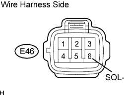
Disconnect the E46 A/C compressor connector.
Measure the resistance of the connector.
- Standard resistance:
Tester Connection
| Condition
| Specified Condition
|
3 (SOL+) - 6 (SOL-)
| 20°C (68°F)
| 10 to 11 Ω
|
3UZ-FE
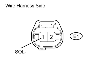
Disconnect the E1 A/C compressor connector.
Measure the resistance of the connector.
- Standard resistance:
Tester Connection
| Condition
| Specified Condition
|
2 (SOL+) - 1 (SOL-)
| 20°C (68°F)
| 10 to 11 Ω
|
| 3.CHECK WIRE HARNESS (A/C COMPRESSOR - BODY GROUND) |
3GR-FE, 3GR-FSE
Disconnect the E46 A/C compressor connector.
Measure the resistance of the wire harness connector.
- Standard resistance:
Tester Connection
| Condition
| Specified Condition
|
E46-6 (SOL-) - Body ground
| Always
| Below 1 Ω
|
3UZ-FE
Disconnect the E1 A/C compressor connector.
Measure the resistance of the wire harness connector.
- Standard resistance:
Tester Connection
| Condition
| Specified Condition
|
E1-1 (SOL-) - Body ground
| Always
| Below 1 Ω
|
| | REPAIR OR REPLACE HARNESS AND CONNECTOR |
|
|
| 4.CHECK WIRE HARNESS (A/C COMPRESSOR - A/C AMPLIFIER) |
Disconnect the E46 or E1 A/C compressor connector.
Disconnect the L52 A/C amplifier connector.
Measure the resistance of the wire harness side connectors.
- Standard resistance:
Tester Connection
| Condition
| Specified Condition
|
L52-5 (SOL+) - E1-2 (SOL+) (*2)
| Always
| Below 1 Ω
|
L52-5 (SOL+) - E46-3 (SOL+) (*1)
| Always
| Below 1 Ω
|
- HINT:
- *1: 3GR-FE, 3GR-FSE
- *2: 3UZ-FE
| | REPAIR OR REPLACE HARNESS AND CONNECTOR |
|
|
| OK |
|
|
|
| REPLACE AIR CONDITIONING AMPLIFIER |
|