Dtc C1528 Motor Rotation Angle Sensor Malfunction
Steering. Lexus Gs430, Gs300. Uzs190 Grs190
DESCRIPTION
WIRING DIAGRAM
INSPECTION PROCEDURE
CHECK POWER STEERING EARTH WIRE (POWER STEERING LINK ASSEMBLY - BODY GROUND)
CHECK HARNESS AND CONNECTOR (POWER STEERING ECU ASSEMBLY - MOTOR ROTATION ANGLE SENSOR)
INSPECT POWER STEERING LINK ASSEMBLY (MOTOR ROTATION ANGLE SENSOR)
REPLACE POWER STEERING ECU ASSEMBLY
INITIALIZE ROTATION ANGLE SENSOR AND CALIBRATE TORQUE SENSOR ZERO POINT
RECONFIRM DTC
DTC C1528 Motor Rotation Angle Sensor Malfunction |
DESCRIPTION
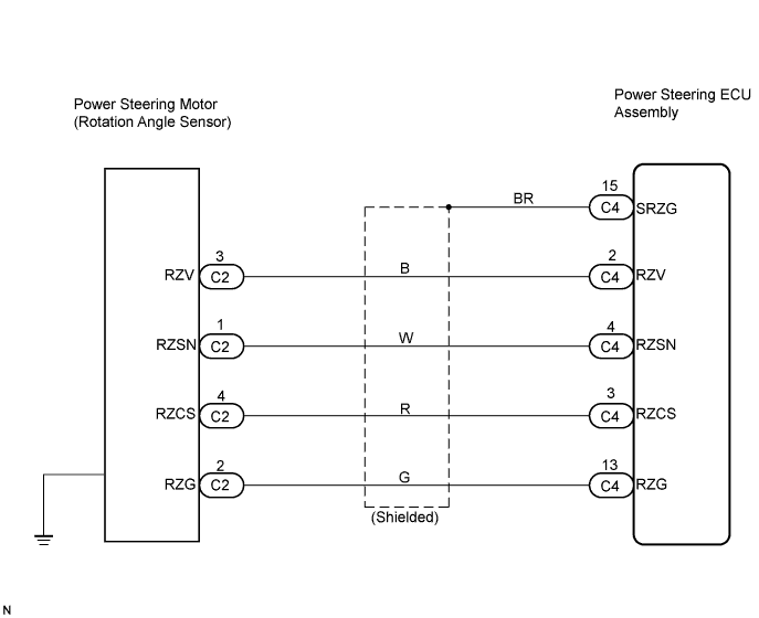
The motor rotation angle sensor detects the motor rotation angle and sends this information to the power steering ECU assembly.DTC No.
| DTC Detection Item
| Trouble Area
|
C1528
| Motor rotation angle sensor malfunction
(e.g. An open, short to ground, or short to B+ in the rotation angle sensor circuit)
| - Motor rotation angle sensor (built into power steering link assembly)
- Wire harness or connector
- Power steering earth wire
- Power steering ECU assembly
|
WIRING DIAGRAM
INSPECTION PROCEDURE
| 1.CHECK POWER STEERING EARTH WIRE (POWER STEERING LINK ASSEMBLY - BODY GROUND) |
Check the installation condition of the power steering earth wire connected to the power steering link assembly.
- OK:
- The power steering earth wire is securely installed to the power steering link assembly and body ground.
| | REINSTALL POWER STEERING EARTH WIRE |
|
|
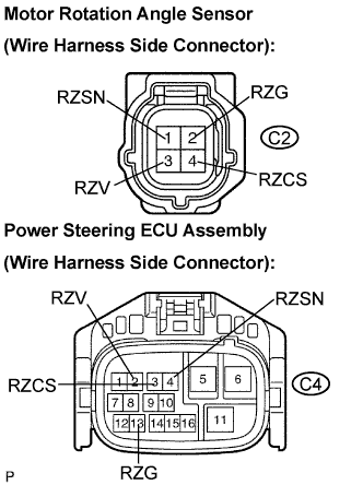
| 2.CHECK HARNESS AND CONNECTOR (POWER STEERING ECU ASSEMBLY - MOTOR ROTATION ANGLE SENSOR) |
Disconnect the C2 connector from the power steering link assembly.
Disconnect the C4 connector from the power steering ECU.
Measure the resistance according to the value(s) in the table below.
- Resistance:
Tester connection
(Symbols)
| Condition
| Specified condition
|
C2-1 (RZSN) - C4-4 (RZSN)
| Always
| Below 1 Ω
|
C2-2 (RZG) - C4-13 (RZG)
| Always
| Below 1 Ω
|
C2-3 (RZV) - C4-2 (RZV)
| Always
| Below 1 Ω
|
C2-4 (RZCS) - C4-3 (RZCS)
| Always
| Below 1 Ω
|
C2-1 (RZSN) - Body ground
| Always
| 10 kΩ or higher
|
C2-2 (RZG) - Body ground
| Always
| 10 kΩ or higher
|
C2-3 (RZV) - Body ground
| Always
| 10 kΩ or higher
|
C2-4 (RZCS) - Body ground
| Always
| 10 kΩ or higher
|
| | REPAIR OR REPLACE HARNESS OR CONNECTOR |
|
|
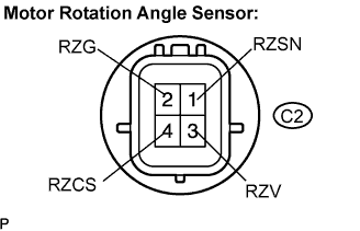
| 3.INSPECT POWER STEERING LINK ASSEMBLY (MOTOR ROTATION ANGLE SENSOR) |
Measure the resistance according to the value(s) in the table below.
- Resistance:
Tester connection
(Symbols)
| Condition
| Specified condition
|
C2-1 (RZSN) - C2-2 (RZG)
| Always
| 50 to 140 Ω
|
C2-3 (RZV) - C2-2 (RZG)
| Always
| 50 to 140 Ω
|
C2-4 (RZCS) - C2-2 (RZG)
| Always
| 15 to 45 Ω
|
- NOTICE:
- If replacing the power steering link assembly, clear the rotation angle sensor calibration value, initialize the rotation angle sensor, and calibrate the torque sensor zero point (Click here).
- 3UZ-FE:
If replacing the power steering link assembly, perform VGRS actuator angle initialization and VGRS actuator angle neutral calibration after wheel alignment adjustment (Click here for INITIALIZATION, Click here for CALIBRATION).
| | REPLACE POWER STEERING LINK ASSEMBLY |
|
|
| 4.REPLACE POWER STEERING ECU ASSEMBLY |
Replace the power steering ECU assembly (Click here).
| 5.INITIALIZE ROTATION ANGLE SENSOR AND CALIBRATE TORQUE SENSOR ZERO POINT |
Initialize the rotation angle sensor and calibrate the torque sensor zero point (Click here).
Check for DTCs (Click here).
Is DTC C1528 output?
- OK:
- DTC is not output.
- NOTICE:
- If replacing the power steering link assembly, clear the rotation angle sensor calibration value, initialize the rotation angle sensor, and calibrate the torque sensor zero point (Click here).
- 3UZ-FE:
If replacing the power steering link assembly, perform VGRS actuator angle initialization and VGRS actuator angle neutral calibration after wheel alignment adjustment (Click here for INITIALIZATION, Click here for CALIBRATION).
| | REPLACE POWER STEERING LINK ASSEMBLY |
|
|