Steering Column Assembly (For 3Gr-Fse) Removal
Steering. Lexus Gs430, Gs300. Uzs190 Grs190
PRECAUTION
PLACE FRONT WHEELS FACING STRAIGHT AHEAD
DISCONNECT CABLE FROM NEGATIVE BATTERY TERMINAL
REMOVE CONSOLE UPPER PANEL GARNISH FRONT
REMOVE CONSOLE UPPER PANEL SUB-ASSEMBLY
REMOVE INSTRUMENT PANEL FINISH PANEL END LH
REMOVE FRONT DOOR SCUFF PLATE LH
REMOVE FRONT DOOR OPENING TRIM COVER LH
REMOVE INSTRUMENT SIDE PANEL LH
REMOVE INSTRUMENT PANEL UNDER COVER SUB-ASSEMBLY NO.1
REMOVE INSTRUMENT PANEL SAFETY PAD SUB-ASSEMBLY NO.1
REMOVE INSTRUMENT PANEL AIRBAG ASSEMBLY LOWER NO.1
REMOVE STEERING WHEEL COVER LOWER NO.2
REMOVE STEERING WHEEL COVER LOWER NO.3
REMOVE STEERING WHEEL PAD
REMOVE STEERING WHEEL ASSEMBLY
REMOVE STEERING COLUMN COVER
REMOVE TILT AND TELESCOPIC SWITCH
REMOVE TURN SIGNAL SWITCH ASSEMBLY WITH SPIRAL CABLE SUB-ASSEMBLY
REMOVE AIR DUCT NO.1
SEPARATE STEERING INTERMEDIATE SHAFT ASSEMBLY NO.2
REMOVE STEERING COLUMN ASSEMBLY
REMOVE STEERING INTERMEDIATE SHAFT ASSEMBLY NO.2
Steering Column Assembly (For 3Gr-Fse) -- Removal |
(Click here)
| 2. PLACE FRONT WHEELS FACING STRAIGHT AHEAD |
| 3. DISCONNECT CABLE FROM NEGATIVE BATTERY TERMINAL |
(Click here)
| 4. REMOVE CONSOLE UPPER PANEL GARNISH FRONT |
Using a clip remover, detach the claws and remove the garnish.
- HINT:
- Tape the clip remover tip before use.
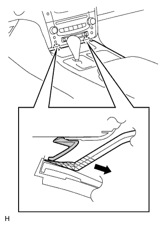
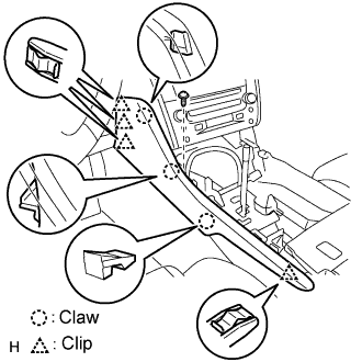
| 5. REMOVE CONSOLE UPPER PANEL SUB-ASSEMBLY |
Twist the shift lever knob in the direction indicated by the arrow and remove it.
Using a screwdriver, detach the 9 clips.
- HINT:
- Tape the screwdriver tip before use.
Remove the ash receptacle and then disconnect the connector.
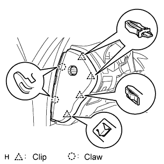
| 6. REMOVE INSTRUMENT PANEL FINISH PANEL END LH |
Remove the screw.
Using a screwdriver, detach the 4 clips and 3 claws.
- HINT:
- Tape the screwdriver tip before use.
Remove the finish panel end.
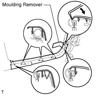
| 7. REMOVE FRONT DOOR SCUFF PLATE LH |
Using a moulding remover, detach the 5 claws and remove the scuff plate.
| 8. REMOVE FRONT DOOR OPENING TRIM COVER LH |
Using a moulding remover, detach the 3 claws and remove the trim cover.
| 9. REMOVE INSTRUMENT SIDE PANEL LH |
Using a screwdriver, detach the 2 claws and 4 clips, and remove the side panel.
- HINT:
- Tape the screwdriver tip before use.
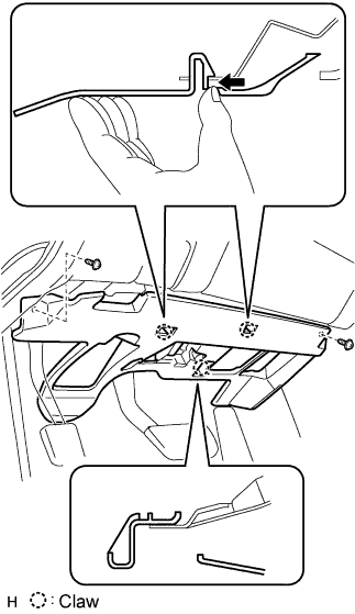
| 10. REMOVE INSTRUMENT PANEL UNDER COVER SUB-ASSEMBLY NO.1 |
Remove the 2 screws.
Detach the 2 claws.
Remove the under cover and then disconnect the connector.
| 11. REMOVE INSTRUMENT PANEL SAFETY PAD SUB-ASSEMBLY NO.1 |
Using a screwdriver, detach the 8 clips and claw.
- HINT:
- Tape the screwdriver tip before use.
Remove the hood lock control cable from the safety pad.
Remove the safety pad.
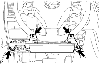
| 12. REMOVE INSTRUMENT PANEL AIRBAG ASSEMBLY LOWER NO.1 |
Remove the 4 bolts and driver side knee airbag assembly.
Disconnect the connector.
- NOTICE:
- When handling the airbag connector, take care not to damage the airbag wire harness.
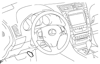
| 13. REMOVE STEERING WHEEL COVER LOWER NO.2 |
Using a screwdriver, remove the steering wheel No.2 cover lower.
- HINT:
- Tape up the screwdriver tip before use.
| 14. REMOVE STEERING WHEEL COVER LOWER NO.3 |
Using a screwdriver, remove the steering wheel No.3 cover lower.
- HINT:
- Tape up the screwdriver tip before use.
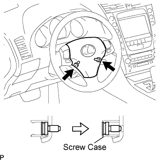
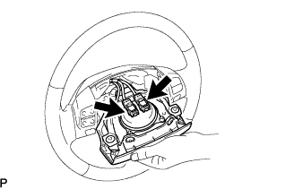
| 15. REMOVE STEERING WHEEL PAD |
Using a "torx" socket wrench (T30), loosen the 2 "torx" screws until the groove along the screw circumference catches on the screw case.
Pull out the steering pad from the steering wheel assembly and support the steering pad with one hand as shown in the illustration.
- NOTICE:
- When removing the steering pad, do not pull the airbag wire harness.
Disconnect the horn connector.
Disconnect the 2 connectors and remove the steering pad.
- NOTICE:
- When handling the airbag connector, take care not to damage the airbag wire harness.
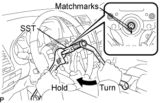
| 16. REMOVE STEERING WHEEL ASSEMBLY |
Remove the steering wheel assembly set nut.
Put matchmarks on the steering wheel assembly and main shaft assembly.
Using SST, remove the steering wheel assembly.
- SST
- 09950-50013(09951-05010,09952-05010,09953-05020,09954-05011)
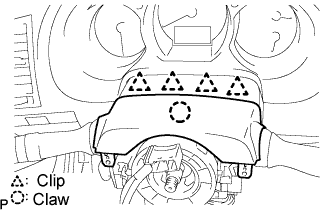
| 17. REMOVE STEERING COLUMN COVER |
Remove the 3 screws.
Disengage the 2 claws to remove the steering column cover lower.
- NOTICE:
- Do not damage the tilt and telescopic switch.
Disengage the 4 clips to separate the steering column cover upper.
Disengage the claw to remove the steering column cover upper.
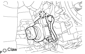
| 18. REMOVE TILT AND TELESCOPIC SWITCH |
Disconnect the connector.
Using a screwdriver, disengage the claw and pull out the tilt and telescopic switch.
- NOTICE:
- Pushing on the claw too hard will break the claw.
- HINT:
- Tape the screwdriver tip before use.
| 19. REMOVE TURN SIGNAL SWITCH ASSEMBLY WITH SPIRAL CABLE SUB-ASSEMBLY |
Remove the clamp and turn signal switch assembly with spiral cable sub-assembly from the steering column assembly.
Disengage the 2 claws and remove the air duct No.1.
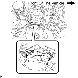
| 21. SEPARATE STEERING INTERMEDIATE SHAFT ASSEMBLY NO.2 |
Loosen bolt (A) and remove bolt (B), then slide the steering intermediate shaft assembly No.2.
- HINT:
- Do not remove bolt (A).
- Do not disconnect the steering intermediate shaft assembly No.2 from the power steering link assembly.
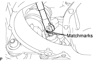
Put matchmarks on the steering sliding yoke sub-assembly and the power steering link assembly.
Separate the steering sliding yoke sub-assembly from the power steering link assembly.
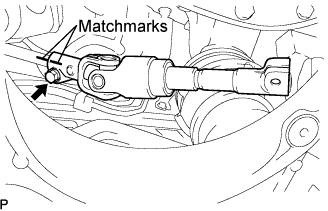
Put matchmarks on the steering sliding yoke sub-assembly and the steering intermediate shaft assembly No.2.
Remove the bolt and the steering sliding yoke sub-assembly from the steering intermediate shaft assembly No.2.
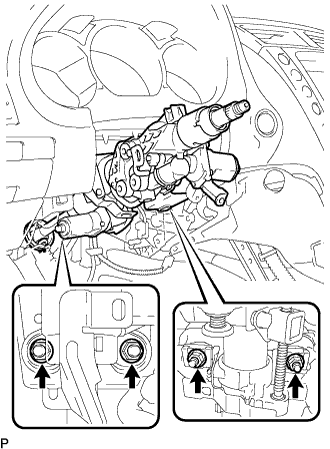
| 22. REMOVE STEERING COLUMN ASSEMBLY |
Remove the bolt and separate the steering intermediate shaft assembly No.2.
Disconnect the connectors and wire harness clamps.
Remove the 4 nuts and steering column assembly from the instrument panel reinforcement assembly.
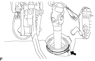
| 23. REMOVE STEERING INTERMEDIATE SHAFT ASSEMBLY NO.2 |
Remove the clamp from the steering column hole shield.
Remove the steering intermediate shaft assembly No.2.