Rear No. 1 Upper Control Arm Installation
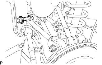
TEMPORARILY TIGHTEN REAR NO. 1 UPPER CONTROL ARM
TEMPORARILY TIGHTEN REAR SHOCK ABSORBER WITH COIL SPRING
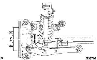
STABILIZE SUSPENSION
FULLY TIGHTEN REAR NO. 1 UPPER CONTROL ARM
FULLY TIGHTEN REAR SHOCK ABSORBER WITH COIL SPRING
INSTALL DIFFERENTIAL NO.2 SUPPORT PROTECTOR
INSTALL REAR WHEEL
INSPECT AND ADJUST REAR WHEEL ALIGNMENT
Rear No. 1 Upper Control Arm -- Installation |
| 1. TEMPORARILY TIGHTEN REAR NO. 1 UPPER CONTROL ARM |
Temporarily install the rear No.1 upper control arm with the bolts, nuts and washers.
Temporarily install the rear No.1 upper control arm with the bolts, nuts and washers.
- NOTICE:
- Push the axle carrier downward.
| 2. TEMPORARILY TIGHTEN REAR SHOCK ABSORBER WITH COIL SPRING |
Temporarily install the rear shock absorber with coil spring with the bolt and nut.
Temporarily install the rear stabilizer link assembly and the load sensing valve sensor bracket to the rear No.2 suspension arm assembly with the bolt and nut.
Jack up the axle carrier, with a wooden block placed between the jack and axle carrier, to apply load to the suspension so that the rear drive shaft assembly becomes level.
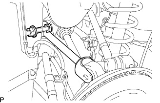
| 4. FULLY TIGHTEN REAR NO. 1 UPPER CONTROL ARM |
Fully tighten the nut on the rear No.1 upper control arm assembly.
- Torque:
- 161 N*m{1,640 kgf*cm, 119 ft.*lbf}
Fully tighten the nut on the rear No.1 upper control arm assembly.
- Torque:
- 161 N*m{1,640 kgf*cm, 119 ft.*lbf}
| 5. FULLY TIGHTEN REAR SHOCK ABSORBER WITH COIL SPRING |
Fully tighten the bolt holding the rear shock absorber with coil spring.
- Torque:
- 110 N*m{1,120 kgf*cm, 81 ft.*lbf}
- NOTICE:
- Turn the bolt while holding the nut.
Fully tighten the nut holding the rear stabilizer link assembly.
- Torque:
- 27 N*m{275 kgf*cm, 20 ft.*lbf}
| 6. INSTALL DIFFERENTIAL NO.2 SUPPORT PROTECTOR |
Install the differential No.2 support protector with the 2 nuts.
- Torque:
- 103 N*m{1,050 kgf*cm, 76 ft.*lbf}
| 8. INSPECT AND ADJUST REAR WHEEL ALIGNMENT |
(Click here)