Front Shock Absorber Installation
TEMPORARILY TIGHTEN FRONT SHOCK ABSORBER WITH COIL SPRING
INSTALL ABSORBER CONTROL ACTUATOR (for AVS)
INSTALL SHOCK ABSORBER CAP UPPER (for AVS)
CONNECT FRONT SUSPENSION UPPER ARM
CONNECT SPEED SENSOR FRONT
CONNECT HEIGHT CONTROL SENSOR LINK SUB-ASSEMBLY FRONT
STABILIZE SUSPENSION
FULLY TIGHTEN FRONT SHOCK ABSORBER WITH COIL SPRING
INSTALL ENGINE ROOM SIDE COVER
INSTALL FRONT WHEEL
CONNECT CABLE TO NEGATIVE BATTERY TERMINAL
HEADLIGHT AIMING INSPECTION
HEADLIGHT AIMING ADJUSTMENT
INSPECT VEHICLE STABILITY CONTROL SYSTEM
INSPECT ADAPTIVE VARIABLE SUSPENSION SYSTEM
PERFORM INITIALIZATION
INSPECT AND ADJUST FRONT WHEEL ALIGNMENT
Front Shock Absorber -- Installation |
| 1. TEMPORARILY TIGHTEN FRONT SHOCK ABSORBER WITH COIL SPRING |
Install the front shock absorber with front coil spring on the vehicle by tightening the 3 nuts on the suspension support side.
- Torque:
- 67 N*m{683 kgf*cm, 49 ft.*lbf}
Insert the bolt from the rear of the vehicle, and install the front shock absorber lower side on the front suspension lower arm.
Temporarily tighten the nut while holding the bolt.
Tighten a lock nut.
- Torque:
- 28 N*m{286 kgf*cm, 21 ft.*lbf}
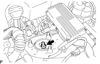
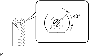
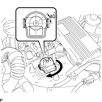
| 2. INSTALL ABSORBER CONTROL ACTUATOR (for AVS) |
Check that the rod position is as shown.
Install the absorber control actuator to the actuator support bracket.
Turn the actuator clockwise 40° until a click is felt.
- NOTICE:
- Do not turn the actuator more than 40°.
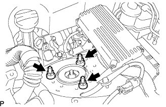
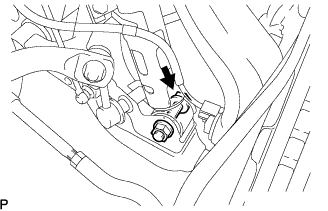
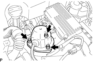
| 3. INSTALL SHOCK ABSORBER CAP UPPER (for AVS) |
Connect the connector.
Install the front shock absorber cap upper with the 3 nuts.
- Torque:
- 20 N*m{202 kgf*cm, 15 ft.*lbf}
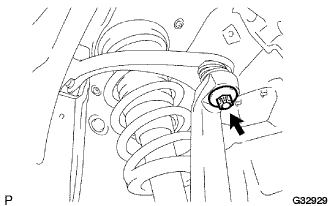
| 4. CONNECT FRONT SUSPENSION UPPER ARM |
Install the steering knuckle to the front suspension upper arm, and tighten it with the nut.
- Torque:
- 87 N*m{887 kgf*cm, 64 ft.*lbf}
Install a new clip to the steering knuckle.
- NOTICE:
- Further tighten the nut up to 60° if the holes for the cotter pin are not aligned.
| 5. CONNECT SPEED SENSOR FRONT |
Install the speed sensor front to the front shock absorber with coil spring with the bolt.
- Torque:
- 6.0 N*m{61 kgf*cm, 53 in.*lbf}
- NOTICE:
- Do not twist the speed sensor front wire harness while installing.
- Be careful not to deform the bracket of the front shock absober with coil spring when installing the bolts.
| 6. CONNECT HEIGHT CONTROL SENSOR LINK SUB-ASSEMBLY FRONT |
Connect the height control sensor link sub-assembly front with the nut.
- Torque:
- 5.4 N*m{55 kgf*cm, 48 in.*lbf}
Install the front wheel.
- Torque:
- 103 N*m{1,050 kgf*cm, 76 ft.*lbf}
Lower the vehicle and bounce it up and down several times to stabilize the front suspension.
Remove the front wheel.
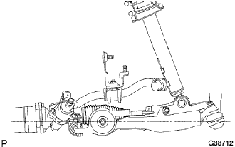
Jack up the front suspension lower arm placing a wooden block in between. Apply a load to the front suspension so that the front suspension lower arm is placed in a horizontal position.
| 8. FULLY TIGHTEN FRONT SHOCK ABSORBER WITH COIL SPRING |
Fully tighten the bolt on the lower side of the front shock absorber while holding the nut.
- Torque:
- 157 N*m{1,600 kgf*cm, 116 ft.*lbf}
| 9. INSTALL ENGINE ROOM SIDE COVER |
- Torque:
- 103 N*m{1,050 kgf*cm, 76 ft.*lbf}
| 11. CONNECT CABLE TO NEGATIVE BATTERY TERMINAL |
| 12. HEADLIGHT AIMING INSPECTION |
Cover or disconnect the connector of the headlight on the opposite side to prevent light from the head-light not being inspected from affecting the headlight aiming inspection.
- NOTICE:
- Do not keep the headlight covered for more than 3 minutes. The headlight lens is made of synthetic resin, and may easily melt or be damaged due to heat.
- HINT:
- When checking the aim of the high-beam, cover the low-beam or disconnect the connector.
Start the engine.
- NOTICE:
- Engine rpm must be 1,500 or more.
w/ headlight leveling switch:
Set the headlight leveling switch to 0 (zero).
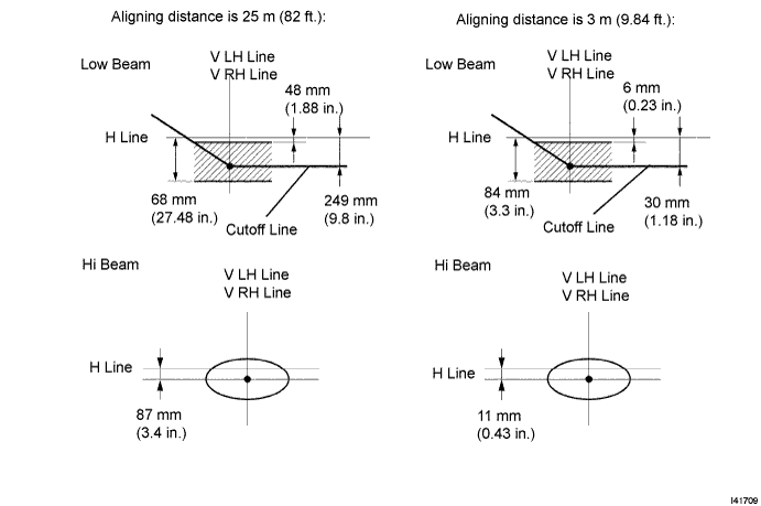
Turn on the headlight and make sure that the cutoff line falls within the specified area, as shown in the illustration.
- HINT:
- Alignment distance is 25 m (82 ft.):
The cutoff line is 48 mm (1.88 in.) to 698 mm (27.48 in.) below the H line with low-beam.
- Alignment distance is 3 m (9.84 ft.):
The cutoff line is 6 mm (0.23 in.) to 84 mm (3.3 in.) below the H line with low-beam.
- Alignment distance is 25 m (82 ft.):
The cutoff line is 249 mm (9.8 in.) below the H line with low-beam.
- Alignment distance is 3 m (9.84 ft.):
The cutoff line is 30 mm (1.88 in.) below the H line with low-beam.
- Since the low-beam light and the high-beam light are a unit, if the aim of either one is correct, the other should also be correct. However, check both beams just to make sure.
| 13. HEADLIGHT AIMING ADJUSTMENT |
Adjust the aim vertically:
Adjust the headlight aim into the specified range by turning aiming screw A with a screwdriver.
- NOTICE:
- The final turn of the aiming screw should be made in the clockwise direction. If the screw is tightened excessively, loosen and then retighten it so that the final turn of the screw is in the clockwise direction.
- HINT:
- Perform the low-beam aim adjustment.
- The headlight aim moves up when turning the aiming screw clockwise, and moves down when turning the aiming screw counterclockwise.
Adjust the aim horizontally:
Adjust the headlight aim into the specified range by turning aiming screw B with a screwdriver.
- NOTICE:
- The final turn of the aiming screw should be made in the clockwise direction. If the screw is tightened excessively, loosen and then retighten it, so that the final turn of the screw is in the clockwise direction.
- HINT:
- Perform the low-beam aim adjustment.
| 14. INSPECT VEHICLE STABILITY CONTROL SYSTEM |
(Click here)
| 15. INSPECT ADAPTIVE VARIABLE SUSPENSION SYSTEM |
(Click here)
| 16. PERFORM INITIALIZATION |
(Click here)
| 17. INSPECT AND ADJUST FRONT WHEEL ALIGNMENT |
(Click here)