REMOVE INSTRUMENT PANEL UNDER COVER SUB-ASSEMBLY NO.2 (for LHD)
REMOVE INSTRUMENT PANEL UNDER COVER SUB-ASSEMBLY NO.1 (for RHD)
INSTALL INSTRUMENT PANEL UNDER COVER SUB-ASSEMBLY NO.2 (for LHD)
INSTALL INSTRUMENT PANEL UNDER COVER SUB-ASSEMBLY NO.1 (for RHD)
Absorber Control Ecu -- Replacement |
| 1. DISCONNECT CABLE FROM NEGATIVE BATTERY TERMINAL |
| 2. REMOVE FRONT DOOR SCUFF PLATE RH |
- HINT:
- Use the same procedures described for the LH side.
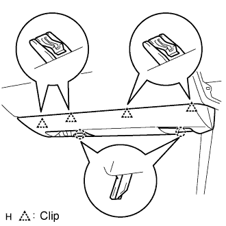
| 3. REMOVE INSTRUMENT PANEL UNDER COVER SUB-ASSEMBLY NO.2 (for LHD) |
 |
Using a screwdriver, detach the 4 clips.
- HINT:
- Tape the screwdriver tip before use.
Disconnect the connector and clamp, and remove the under cover.
| 4. REMOVE INSTRUMENT PANEL UNDER COVER SUB-ASSEMBLY NO.1 (for RHD) |
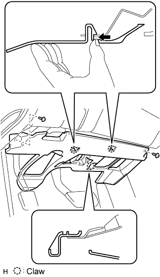 |
Remove the 2 screws.
Detach the 2 claws.
Remove the under cover and then disconnect the connector.
| 5. REMOVE ABSORBER CONTROL ECU |
Turn back the floor carpet to remove the absorber control ECU.
Disengage the 2 clamps to remove the wire harness from the vehicle body.
- NOTICE:
- Do not apply an excessive force to the wire harness.
 |
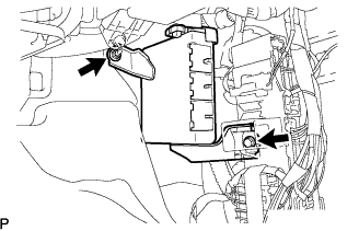
Disconnect the connectors from the absorber control ECU.
Remove the bolt, nut and the absorber control ECU.
 |
| 6. INSTALL ABSORBER CONTROL ECU |
Install the absorber control ECU with the bolt and nut.
- Torque:
- Bolt:
- 8.5 N*m{87 kgf*cm, 75 in.*lbf}
- Nut:
- 6.0 N*m{61 kgf*cm, 53 in.*lbf}
- NOTICE:
- Avoid any impact to the absorber control ECU.
- Do not drop the absorber control ECU. If it is dropped, replace it with a new one.
|
Connect the connectors to the absorber control ECU.
Engage the 2 clamps to install the wire harness to the vehicle body.
|
Install the floor carpet.
| 7. INSTALL INSTRUMENT PANEL UNDER COVER SUB-ASSEMBLY NO.2 (for LHD) |
 |
Connect the connector and clamp.
Attach the 4 clips to install the under cover.
| 8. INSTALL INSTRUMENT PANEL UNDER COVER SUB-ASSEMBLY NO.1 (for RHD) |
 |
Connect the connectors.
Attach the 2 claws to install the under cover.
Install the 2 screws.
| 9. REMOVE FRONT DOOR SCUFF PLATE RH |
- HINT:
- Use the same procedures described for the LH side.
| 10. CONNECT CABLE TO NEGATIVE BATTERY TERMINAL |
| 11. INSPECT ADAPTIVE VARIABLE SUSPENSION SYSTEM |
| 12. PERFORM INITIALIZATION |