Adaptive Variable Suspension System Tc And Cg Terminal Circuit
DESCRIPTION
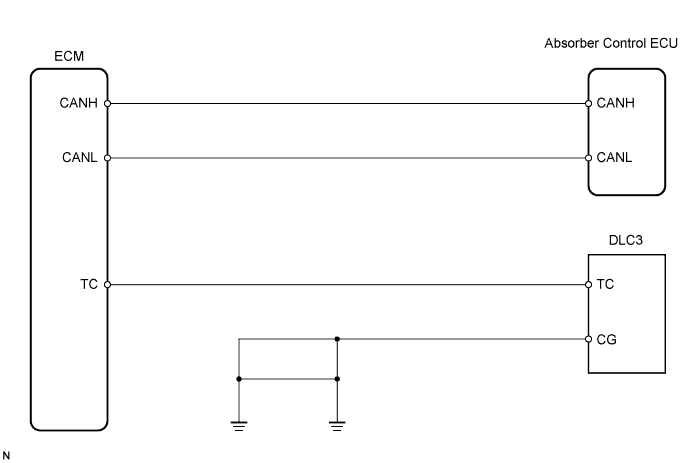
WIRING DIAGRAM
INSPECTION PROCEDURE
INSPECT TERMINAL VOLTAGE (DLC3 TC TERMINAL VOLTAGE)
CHECK HARNESS AND CONNECTOR (ECM TO DLC3)
CHECK CAN COMMUNICATION SYSTEM
CHECK HARNESS AND CONNECTOR (ECM TO DLC3)
CHECK HARNESS AND CONNECTOR (DLC3 TO BODY GROUND)
CHECK ECM (DLC3 TC TERMINAL INPUT)
CHECK CAN COMMUNICATION SYSTEM
ADAPTIVE VARIABLE SUSPENSION SYSTEM - TC and CG Terminal Circuit |
DESCRIPTION
The DTC output mode is set by connecting terminals TC and CG of DLC3.The DTCs are displayed by a blinking of the absorber control indicator light.
WIRING DIAGRAM
INSPECTION PROCEDURE
- NOTICE:
- When replacing the absorber control ECU, check the acceleration sensor assembly signal after replacement (Click here).
- HINT:
- Check the condition of each related circuit connector before troubleshooting (Click here).
| 1.INSPECT TERMINAL VOLTAGE (DLC3 TC TERMINAL VOLTAGE) |
Turn the engine switch on (IG).
Measure the voltage according to the value(s) in the table below.
- Voltage:
Tester Connection
| Condition
| Specified Condition
|
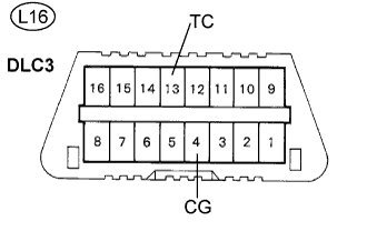
L16-13 (TC) -
L16-4 (CG)
| Engine switch on (IG)
| 10 to 14 V
|
Turn the engine switch off.
Measure the resistance according to the value(s) in the table below.
- Resistance:
Tester Connection
| Specified Condition
|
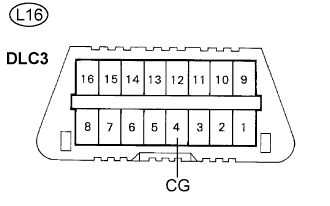
L16-4 (CG) - Body ground
| Below 1 Ω
|
| 2.CHECK HARNESS AND CONNECTOR (ECM TO DLC3) |
Disconnect the ECM connector.
Measure the resistance according to the value(s) in the table below.
- Resistance:
Tester Connection
| Specified Condition
|
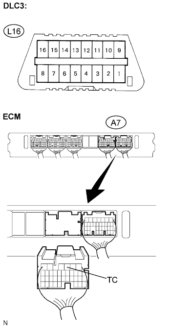
A7-3 (TC) - L16-13 (TC)
| Below 1 Ω
|
L16-13 (TC) - Body ground
| 10 kΩ or higher
|
| | REPAIR OR REPLACE HARNESS OR CONNECTOR (TC TERMINAL CIRCUIT) |
|
|
| 3.CHECK CAN COMMUNICATION SYSTEM |
Check if the CAN communication system DTC is output (Click here).
- Result:
Result
| Proceed To
|
DTC is not output
| A
|
DTC is not output (when troubleshooting accordance with the PROBLEM SYMPTOMS TABLE)
| B
|
DTC is output
| C
|
| | PROCEED TO NEXT CIRCUIT INSPECTION SHOWN IN PROBLEM SYMPTOMS TABLE |
|
|
| | REPAIR CIRCUIT INDICATED BY OUTPUT CODE |
|
|
| A |
|
|
|
| REPLACE ABSORBER CONTROL ECU |
|
| 4.CHECK HARNESS AND CONNECTOR (ECM TO DLC3) |
Disconnect the ECM connector.
Measure the resistance according to the value(s) in the table below.
- Resistance:
Tester Connection
| Specified Condition
|
A7-3 (TC) - L16-13 (TC)
| Below 1 Ω
|
L16-13 (TC) - Body ground
| 10 kΩ or higher
|
| | REPAIR OR REPLACE HARNESS OR CONNECTOR (TC TERMINAL CIRCUIT) |
|
|
| 5.CHECK HARNESS AND CONNECTOR (DLC3 TO BODY GROUND) |
Measure the resistance according to the value(s) in the table below.
- Resistance:
Tester Connection
| Specified Condition
|
L16-4 (CG) - Body ground
| Below 1 Ω
|
| | REPAIR OR REPLACE HARNESS OR CONNECTOR (GND CIRCUIT) |
|
|
| 6.CHECK ECM (DLC3 TC TERMINAL INPUT) |
Using the SST, connect the terminals TC and CG of the DCL3.
- SST
- 09843-18040
Check that the engine, ABS, and VSC warning lights are blinking.
- Result:
Result
| Proceed To
|
Warning lights are blinking
| A
|
Warning lights are not blinking
| B
|
| 7.CHECK CAN COMMUNICATION SYSTEM |
Check if the CAN communication system DTC is output (Click here).
- Result:
Result
| Proceed To
|
DTC is not output
| A
|
DTC is not output (when troubleshooting accordance with the PROBLEM SYMPTOMS TABLE)
| B
|
DTC is output
| C
|
| | PROCEED TO NEXT CIRCUIT INSPECTION SHOWN IN PROBLEM SYMPTOMS TABLE |
|
|
| | REPAIR CIRCUIT INDICATED BY OUTPUT CODE |
|
|
| A |
|
|
|
| REPLACE ABSORBER CONTROL ECU |
|