Adaptive Variable Suspension System Absorber Control Indicator Light Remains On
DESCRIPTION
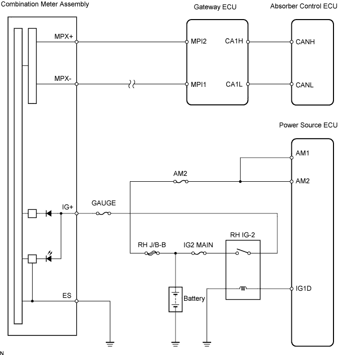
WIRING DIAGRAM
INSPECTION PROCEDURE
CHECK DTC
PERFORM TEST MODE
INSPECT CAN COMMUNICATION SYSTEM
INSPECT MULTIPLEX COMMUNICATION SYSTEM
INSPECT COMBINATION METER ASSEMBLY
ADAPTIVE VARIABLE SUSPENSION SYSTEM - Absorber Control Indicator Light Remains On |
DESCRIPTION
- Check the DTC and make sure that the normal system code is output (Click here).
(If malfunction code is output, Click here).
- If the absorber control ECU stores a DTC, the absorber control indicator light on the combination meter assembly will come on.
- The absorber control ECU is connected to the combination meter assembly via the CAN communication system and multiplex communication system.
WIRING DIAGRAM
INSPECTION PROCEDURE
- NOTICE:
- When replacing the absorber control ECU, check the acceleration sensor assembly signal after replacement (Click here).
- HINT:
- Start the inspection from step 3 when troubleshooting accordance with the PROBLEM SYMPTOMS TABLE.
- Check the condition of each related circuit connector before troubleshooting (Click here).
Check DTC (Click here).
- Result:
Result
| Proceed To
|
DTC is not output
| A
|
DTC is output
| B
|
| | REPAIR CIRCUIT INDICATED BY OUTPUT CODE |
|
|
Perform test mode (Click here).
Check if the test mode DTC C1787/87 is output.
- Result:
Result
| Proceed To
|
DTC C1787/87 is not output
| A
|
DTC C1787/87 is output
| B
|
| | REPAIR CIRCUIT INDICATED BY OUTPUT CODE |
|
|
| 3.INSPECT CAN COMMUNICATION SYSTEM |
Check if the CAN communication system DTC is output (Click here).
- Result:
Result
| Proceed To
|
DTC is not output
| A
|
DTC is output
| B
|
| | REPAIR CIRCUIT INDICATED BY OUTPUT CODE |
|
|
| 4.INSPECT MULTIPLEX COMMUNICATION SYSTEM |
Check if the multiplex communication system DTC is output (Click here).
- Result:
Result
| Proceed To
|
DTC is not output
| A
|
DTC is output
| B
|
| | REPAIR CIRCUIT INDICATED BY OUTPUT CODE |
|
|
| 5.INSPECT COMBINATION METER ASSEMBLY |
Check the combination meter assembly (Click here).
- OK:
- The combination meter assembly is normal.
- Result:
Result
| Proceed To
|
OK
| A
|
OK (when troubleshooting accordance with the PROBLEM SYMPTOMS TABLE)
| B
|
NG
| C
|
| | PROCEED TO NEXT CIRCUIT INSPECTION SHOWN IN PROBLEM SYMPTOMS TABLE |
|
|
| | REPLACE COMBINATION METER ASSEMBLY |
|
|
| A |
|
|
|
| REPLACE ABSORBER CONTROL ECU |
|