Dtc P2716 Pressure Control Solenoid D Electrical (Shift Solenoid Valve Slt)
DESCRIPTION
MONITOR DESCRIPTION
WIRING DIAGRAM
INSPECTION PROCEDURE
INSPECT TRANSMISSION WIRE (SLT)
CHECK HARNESS AND CONNECTOR (TRANSMISSION WIRE - ECM)
INSPECT SHIFT SOLENOID VALVE SLT
DTC P2716 Pressure Control Solenoid "D" Electrical (Shift Solenoid Valve SLT) |
DESCRIPTION
Click here.DTC No.
| DTC Detection Condition
| Trouble Area
|
P2716
| Open or short is detected in shift solenoid valve SLT circuit for 1 second or more while driving (1-trip detection logic).
| - Open or short in shift solenoid valve SLT circuit
- Shift solenoid valve SLT
- ECM
|
MONITOR DESCRIPTION
When an open or short in the linear solenoid valve (SLT) circuit is detected, the ECM interprets this as a fault. The ECM will turn on the MIL and store the DTC.
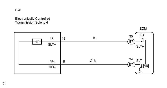
WIRING DIAGRAM
INSPECTION PROCEDURE
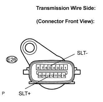
| 1.INSPECT TRANSMISSION WIRE (SLT) |
Disconnect the transmission wire connector from the transmission.
Measure the resistance according to the value(s) in the table below.
- Resistance:
Tester Connection
| Specified Condition
20°C (68°F)
|
13 (SLT+) - 5 (SLT-)
| 5.0 to 5.6 Ω
|
Measure the resistance according to the value(s) in the table below.
- Resistance (Check for short):
Tester Connection
| Specified Condition
|
13 (SLT+) - Body ground
| 10 kΩ or higher
|
5 (SLT-) - Body ground
| ↑
|
| 2.CHECK HARNESS AND CONNECTOR (TRANSMISSION WIRE - ECM) |
Connect the transmission wire connector to the transmission.
Disconnect the ECM connector.
Measure the resistance according to the value(s) in the table below.
- Resistance:
Tester Connection
| Specified Condition
20°C (68°F)
|
E7 - 35 (SLT+) - E7 - 34 (SLT-)
| 5.0 to 5.6 Ω
|
Measure the resistance according to the value(s) in the table below.
- Resistance (Check for short):
Tester Connection
| Specified Condition
|
E7 - 35 (SLT+) - Body ground
| 10 kΩ or higher
|
E7 - 34 (SLT-) - Body ground
| ↑
|
| | REPAIR OR REPLACE HARNESS OR CONNECTOR |
|
|
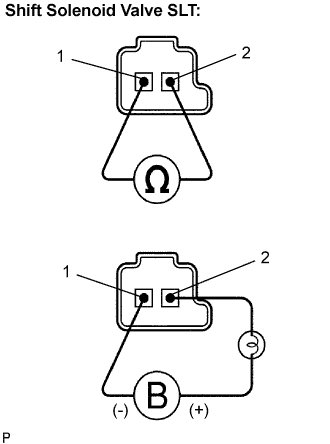
| 3.INSPECT SHIFT SOLENOID VALVE SLT |
Remove the shift solenoid valve SLT.
Measure the resistance according to the value(s) in the table below.
- Resistance:
Tester Connection
| Specified Condition
20°C (68°F)
|
1 - 2
| 5.0 to 5.6 Ω
|
Connect the positive (+) lead with a 21 W bulb to terminal 2 and the negative (-) lead to terminal 1 of the solenoid valve connector, then check the movement of the valve.
- OK:
- The solenoid makes an operating sound.
| | REPLACE SHIFT SOLENOID VALVE SLT |
|
|
| OK |
|
|
|
| REPAIR OR REPLACE TRANSMISSION WIRE |
|