Fuel Injector Installation
Engine. Lexus Gs430, Gs300. Uzs190 Grs190
INSTALL FUEL INJECTOR ASSEMBLY
INSTALL NO. 2 FUEL DELIVERY PIPE SUB-ASSEMBLY
INSTALL FUEL DELIVERY PIPE SUB-ASSEMBLY
INSTALL FUEL PRESSURE PULSATION DAMPER ASSEMBLY
INSTALL INTAKE MANIFOLD
INSTALL NO. 2 FUEL PIPE ASSEMBLY
INSTALL ENGINE WIRE
INSTALL NO. 3 V-BANK COVER BRACKET
INSTALL NO. 2 V-BANK COVER BRACKET
INSTALL NO. 1 VACUUM SWITCHING VALVE ASSEMBLY
INSTALL NO. 1 V-BANK COVER BRACKET
INSTALL NO. 4 V-BANK COVER BRACKET
INSTALL THROTTLE BODY ASSEMBLY
INSTALL INTAKE AIR CONNECTOR PIPE
CONNECT CABLE TO NEGATIVE BATTERY TERMINAL
CHECK FOR FUEL LEAKS
ADD COOLANT
CHECK FOR COOLANT LEAKS
INSTALL V-BANK COVER
INSTALL ENGINE ROOM SIDE COVER RH
INSTALL ENGINE ROOM SIDE COVER LH
INSTALL AIR INTAKE DUCT SEAL
PERFORM INITIALIZATION
Fuel Injector -- Installation |
| 1. INSTALL FUEL INJECTOR ASSEMBLY |
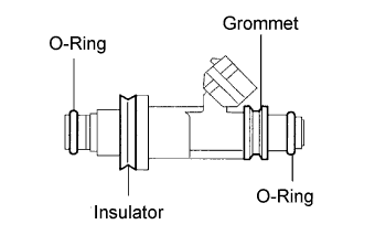
Install a new O-ring, grommet and insulator to the injector.
- NOTICE:
- Check that there is no damage or foreign material in the groove of the injector when installing the injector's O-ring.
- Apply gasoline to a new O-ring and install it to the injector.
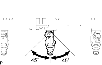
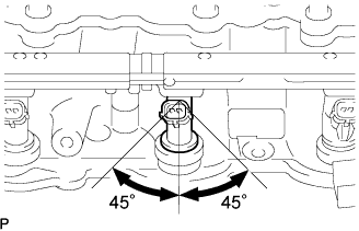
Push and rotate the injector 45° clockwise and counterclockwise to install it to the delivery pipe.
Check that the injector rotates smoothly.
- NOTICE:
- When the injector does not rotate smoothly, the O-ring may be pinched. Remove the injector and install a new O-ring to the injector.
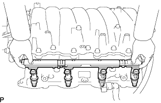
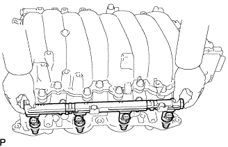
| 2. INSTALL NO. 2 FUEL DELIVERY PIPE SUB-ASSEMBLY |
Install the delivery pipe (with injector) to the intake manifold.
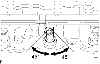
With the condition as stated above, rotate the injector 45° clockwise and counterclockwise.
- NOTICE:
- When the injector does not rotate smoothly, the O-ring may be pinched. Remove the injector and install a new O-ring to the injector.
With the spacer contacting the delivery pipe, install the delivery pipe with the 2 nuts.
- Torque:
- 21 N*m{214 kgf*cm, 15 ft.*lbf}
| 3. INSTALL FUEL DELIVERY PIPE SUB-ASSEMBLY |
Install the delivery pipe (with injector) to the intake manifold.
With the condition as stated above, rotate the injector 45° clockwise and counterclockwise.
- NOTICE:
- When the injector does not rotate smoothly, the O-ring may be pinched. Remove the injector and install a new O-ring to the injector.
With the spacer contacting the delivery pipe, install the delivery pipe with the 2 nuts.
- Torque:
- 21 N*m{214 kgf*cm, 15 ft.*lbf}
| 4. INSTALL FUEL PRESSURE PULSATION DAMPER ASSEMBLY |
Using a wrench, install 4 new gaskets and 2 fuel pulsation dampers to the fuel pipe with the 2 bolts.
- Torque:
- 39 N*m{398 kgf*cm, 29 ft.*lbf}for use without SST33 N*m{337 kgf*cm, 24 ft.*lbf}for use with SST
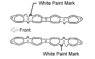
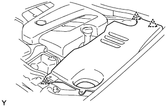
| 5. INSTALL INTAKE MANIFOLD |
Set 2 new gaskets on the cylinder head.
- HINT:
- Make sure the white paint marks are facing upward.
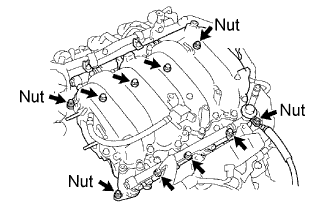
Install the intake manifold to the gasket and cylinder head with the 6 bolts and 4 nuts.
- Torque:
- 18 N*m{184 kgf*cm, 13 ft.*lbf}
Connect the 8 injector connectors.
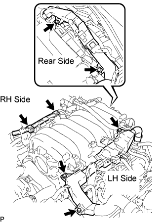
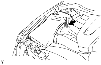
| 6. INSTALL NO. 2 FUEL PIPE ASSEMBLY |
Install the wire protector (LH side) with the 3 bolts.
Install the 2 wire clamps on the engine wire (RH side) to the brackets on the RH delivery pipe.
Install the engine wire protector (rear side) to the rear water by-pass joint and RH cylinder head with the 2 bolts.
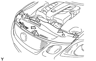
| 8. INSTALL NO. 3 V-BANK COVER BRACKET |
Install the bracket to the manifold with the bolt, as shown in E in the illustration below.
- Torque:
- 7.5 N*m{76 kgf*cm, 66 in.*lbf}
Connect the connector.
| 9. INSTALL NO. 2 V-BANK COVER BRACKET |
Install the bracket to the manifold with the bolt, as shown in D in the illustration below.
- Torque:
- 7.5 N*m{76 kgf*cm, 66 in.*lbf}
| 10. INSTALL NO. 1 VACUUM SWITCHING VALVE ASSEMBLY |
Install the bracket of the VSV to the manifold with the bolt, as shown in C in the illustration below.
- Torque:
- 18 N*m{184 kgf*cm, 13 ft.*lbf}
Connect the vacuum hose to the VSV, as shown in C in the illustration below.
Connect the connector to the VSV, as shown in C in the illustration below.
| 11. INSTALL NO. 1 V-BANK COVER BRACKET |
Install the bracket to the manifold with the bolt, as shown in B in the illustration below.
- Torque:
- 7.5 N*m{76 kgf*cm, 66 in.*lbf}
| 12. INSTALL NO. 4 V-BANK COVER BRACKET |
Install the bracket to the manifold with the 2 nuts, as shown in A in the illustration below.
- Torque:
- 18 N*m{184 kgf*cm, 13 ft.*lbf}
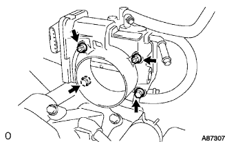
| 13. INSTALL THROTTLE BODY ASSEMBLY |
Install a new gasket and the throttle body with the 2 bolts and 2 nuts.
- Torque:
- 18 N*m{184 kgf*cm, 13 ft.*lbf}
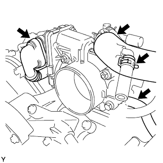
Connect the 2 water by-pass hoses.
Connect the connector and wire.
Connect the PCV hose.
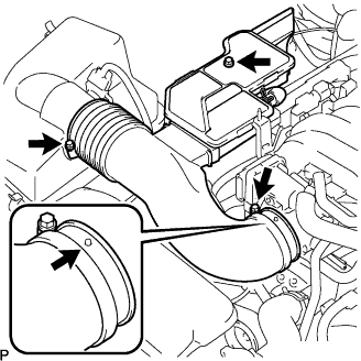
| 14. INSTALL INTAKE AIR CONNECTOR PIPE |
Install the connector pipe with the bolt and 2 hose clamps.
- Torque:
- 4.0 N*m{41 kgf*cm, 35 ft.*lbf} for hose clamps
- 5.0 N*m{51 kgf*cm, 44 ft.*lbf} for bolt
Connect the air hose and No. 1 ventilation hose.
| 15. CONNECT CABLE TO NEGATIVE BATTERY TERMINAL |
Check for fuel leaks (Click here).
| 18. CHECK FOR COOLANT LEAKS |
Check for engine coolant leaks (Click here).
Install the cover with the 2 nuts.
- Torque:
- 5.0 N*m{51 kgf*cm, 44 in.*lbf}
| 20. INSTALL ENGINE ROOM SIDE COVER RH |
Install the side cover with the 2 clips and nut.
| 21. INSTALL ENGINE ROOM SIDE COVER LH |
Install the side cover with the 3 clips.
| 22. INSTALL AIR INTAKE DUCT SEAL |
Install the intake duct seal with the 7 clips.
| 23. PERFORM INITIALIZATION |
Perform initialization (Click here).
- NOTICE:
- Certain systems need to be initialized after disconnecting and reconnecting the cable from the negative (-) battery terminal.