Fuel Injector -- Removal |
| 1. DISCHARGE FUEL SYSTEM PRESSURE |
- NOTICE:
- Perform the following procedures to prevent fuel from spilling out before removing any fuel system parts.
- Pressure will still remain in the fuel line even after performing the following procedures. When disconnecting the fuel line, cover it with a shop rag or a piece of cloth to prevent fuel from spraying.
Remove the F/PMP fuse.
Remove the engine room No. 2 relay block cover upper.
Remove the F/PMP fuse.
Start the engine.
After the engine has stopped, turn the engine switch off.
- HINT:
- DTC P0171/25 (fuel problem) and/or P0191/49 (fuel pressure sensor signal error) may be detected.
Crank the engine again. Check that the engine does not start.
Remove the fuel tank cap to discharge pressure from the fuel tank.
Reinstall the F/PMP fuse.
Disconnect the fuel pump connector.
Remove the rear seat cushion.
Remove the rear floor service hole cover.
Disconnect the fuel pump connector.
Start the engine.
After the engine has stopped, turn the engine switch off.
- HINT:
- DTC P0171/25 (fuel problem) and/or P0191/49 (fuel pressure sensor signal error) may be detected.
Crank the engine again. Check that the engine does not start.
Remove the fuel tank cap to discharge pressure from the fuel tank.
Reconnect the fuel pump connector.
Install the rear floor service hole cover.
Install the rear seat.
| 2. DISCONNECT CABLE FROM NEGATIVE BATTERY TERMINAL |
- CAUTION:
- Wait at least 90 seconds after disconnecting the cable from the negative (-) battery terminal to prevent airbag and seat belt pretensioner activation.
| 3. DRAIN ENGINE COOLANT |
| 4. REMOVE V-BANK COVER |
Remove the 2 nuts and cover.
| 5. REMOVE COOL AIR INTAKE DUCT SEAL |
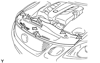 |
Remove the 7 clips and intake duct seal.
| 6. REMOVE ENGINE ROOM SIDE COVER LH |
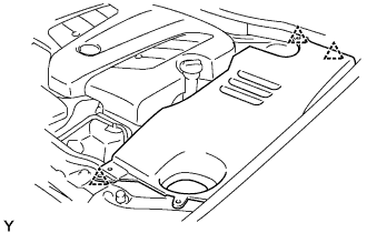 |
Remove the 3 clips and side cover.
| 7. REMOVE ENGINE ROOM SIDE COVER RH |
 |
Remove the nut, 2 clips and side cover.
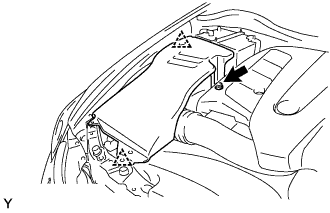
| 8. REMOVE INTAKE AIR CONNECTOR PIPE |
Disconnect the air hose and No. 1 ventilation hose.
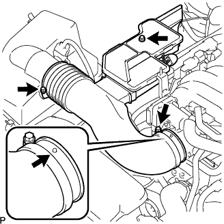 |
Loosen the 2 hose clamps and remove the intake air connector.
| 9. REMOVE THROTTLE WITH MOTOR BODY ASSEMBLY |
Disconnect the PCV hose hose.
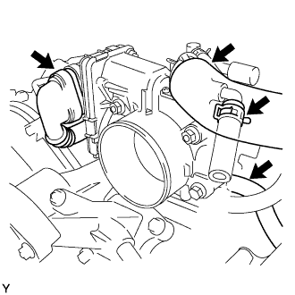 |
Disconnect the connectors and wire.
Disconnect the 2 water by-pass hoses.
Remove the 2 bolts, 2 nuts, throttle body and gasket.
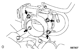 |
| 10. REMOVE NO. 4 V-BANK COVER BRACKET |
Disconnect the connector as shown in A in the illustration below.
Remove the bolt and bracket.
| 11. REMOVE NO. 1 V-BANK COVER BRACKET |
Remove the bolt and bracket as shown in B in the illustration below.
| 12. REMOVE NO. 1 VACUUM SWITCHING VALVE ASSEMBLY |
Disconnect the connector from the VSV, as shown in C in the illustration below.
Disconnect the vacuum hose from the VSV, as shown in C in the illustration below.
Remove the bolt and VSV as shown in C in the illustration below.
| 13. REMOVE NO. 2 V-BANK COVER BRACKET |
Remove the bolt and bracket from the intake manifold, as shown in D in the illustration below.
| 14. REMOVE NO. 3 V-BANK COVER BRACKET |
Disconnect the connector.
Remove the bolt and bracket as shown in E in the illustration below.

| 15. DISCONNECT ENGINE WIRE |
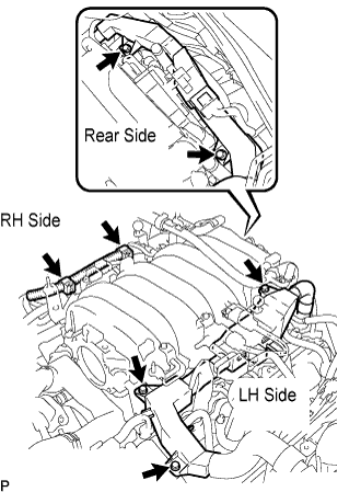 |
Remove the 3 bolts and disconnect the engine wire protector (LH side) from the intake manifold upper and camshaft bearing cap.
Disconnect the 2 wire clamps on the engine wire (RH side) from the brackets on the RH delivery pipe.
Remove the 2 bolts and disconnect the engine wire protector (rear side) from the rear water by-pass joint and RH cylinder head.
| 16. REMOVE FUEL PRESSURE PULSATION DAMPER ASSEMBLY |
Using a wrench, remove the 2 pressure pulsation dampers.
Remove the fuel delivery pipe, fuel pipe and gasket.
| 17. DISCONNECT NO. 2 FUEL PIPE SUB-ASSEMBLY |
| 18. REMOVE INTAKE MANIFOLD |
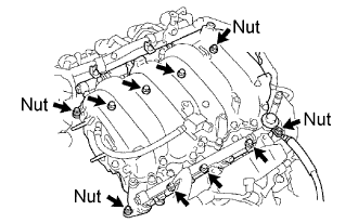 |
Disconnect the 8 injector connectors.
Remove the 6 bolts, 4 nuts, intake manifold and 2 gaskets.
| 19. REMOVE FUEL DELIVERY PIPE SUB-ASSEMBLY |
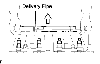 |
Remove the 2 nuts and fuel delivery pipe.
- NOTICE:
- When removing the delivery pipe, hold the pipe by both ends and pull it straight upward.
| 20. REMOVE NO. 2 DELIVERY PIPE SUB-ASSEMBLY |
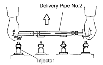 |
Remove the 2 nuts and fuel delivery pipe.
- NOTICE:
- When removing the delivery pipe, hold the pipe by both ends and pull it straight upward.
| 21. REMOVE FUEL INJECTOR ASSEMBLY |
Remove the 8 fuel injectors from the intake manifold.
- NOTICE:
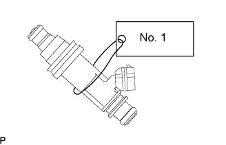
- When removing an injector, do not apply force in a lateral direction.
- For reinstallation purposes, attach a tag or label to the injector shaft.
Remove the O-ring, grommet and insulator.
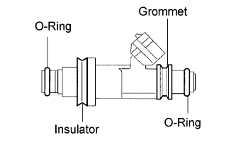 |