Engine. Lexus Gs430, Gs300. Uzs190 Grs190
DISCHARGE FUEL SYSTEM PRESSURE
DISCONNECT CABLE FROM NEGATIVE BATTERY TERMINAL
REMOVE REAR SEAT CUSHION ASSEMBLY
REMOVE ROOM NO. 3 PARTITION PAD
REMOVE REAR FLOOR NO. 2 SERVICE HOLE COVER
REMOVE FUEL SUCTION TUBE WITH PUMP AND GAUGE ASSEMBLY
REMOVE REAR FLOOR SERVICE HOLE COVER
REMOVE FUEL RETURN VENT TUBE SUB-ASSEMBLY
REMOVE EXHAUST PIPE ASSEMBLY
REMOVE FRONT FLOOR COVER CENTER RH
REMOVE FRONT FLOOR NO. 1 HEAT INSULATOR
REMOVE PROPELLER WITH CENTER BEARING SHAFT ASSEMBLY
REMOVE NO. 2 FUEL TANK PROTECTOR
REMOVE NO. 1 DIFFERENTIAL SUPPORT PROTECTOR
REMOVE NO. 2 DIFFERENTIAL SUPPORT PROTECTOR
REMOVE REAR FLOOR SIDE MEMBER COVER LH
REMOVE REAR FLOOR SIDE MEMBER COVER RH
DISCONNECT PARKING BRAKE CABLE ASSEMBLY
DISCONNECT FUEL TANK MAIN TUBE SUB-ASSEMBLY
DISCONNECT FUEL TANK TO FILLER PIPE HOSE
REMOVE FUEL EMISSION HOSE
REMOVE FUEL TANK SUB-ASSEMBLY
REMOVE FUEL TANK MAIN TUBE SUB-ASSEMBLY
REMOVE FUEL TANK CUSHION
REMOVE NO. 1 FUEL TANK PROTECTOR
| 1. DISCHARGE FUEL SYSTEM PRESSURE |
- CAUTION:
- Do not disconnect any part of the fuel system until you have discharged the fuel system pressure.
- Even after discharging the fuel pressure, place a cloth or equivalent over fittings as you separate them to reduce the risk of fuel spray on yourself or in the engine compartment.
Disconnect the cable from the negative (-) battery terminal.
- CAUTION:
- Wait at least 90 seconds after disconnecting the cable from the negative (-) battery terminal to prevent airbag and seat belt pretensioner activation.
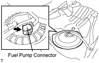
Disconnect the fuel pump connector.
Connect the cable to the negative (-) battery terminal.
Start the engine. After the engine has stopped on its own, turn the engine switch off.
- NOTICE:
- DTC P0171/P0172 (system too lean) may be set.
Crank the engine again, then check that the engine does not start.
Loosen the fuel tank cap, then discharge the pressure in the fuel tank completely.
Connect the fuel pump connector.
| 2. DISCONNECT CABLE FROM NEGATIVE BATTERY TERMINAL |
- CAUTION:
- Wait at least 90 seconds after disconnecting the cable from the negative (-) battery terminal to prevent airbag activation.
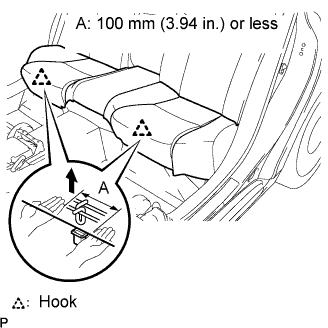
| 3. REMOVE REAR SEAT CUSHION ASSEMBLY |
Detach the seat cushion's 2 front hooks from the vehicle body.
- NOTICE:
- Follow the instructions below carefully as the cushion frame deforms easily.
Choose a hook to detach first. Place your hands near the hook as shown in the illustration. Then lift the seat cushion to detach the hook.
Repeat for the other hook.
Detach the seat cushion's 2 rear hooks from the seatback.
Remove the seat cushion.
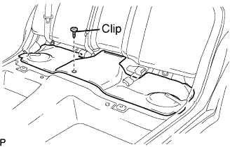
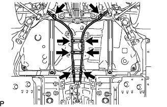
| 4. REMOVE ROOM NO. 3 PARTITION PAD |
Remove the clip and room partition pad.
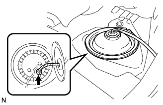
| 5. REMOVE REAR FLOOR NO. 2 SERVICE HOLE COVER |
Remove the service hole cover and disconnect the fuel pump connector.
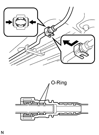
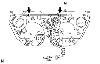
| 6. REMOVE FUEL SUCTION TUBE WITH PUMP AND GAUGE ASSEMBLY |
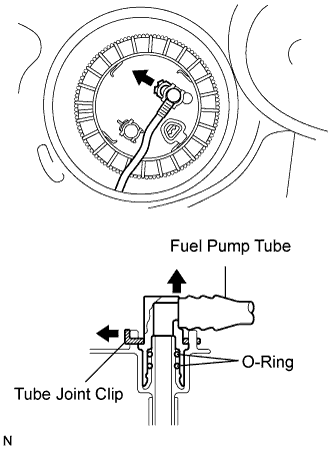
Disconnect the fuel tank main tube.
Remove the tube joint clip and fuel tube.
- NOTICE:
- Remove any dirt and foreign matter on the fuel tube joint before performing this work.
- Do not allow any scratches or foreign matter on the parts when disconnecting them, as the fuel tube joint has the O-rings that seals the plug.
- Perform this work by hand. Do not use any tools.
- Do not forcibly bend, twist or turn the nylon tube.
- Protect the disconnected part by covering it with a plastic bag and tape after disconnecting the fuel tubes.
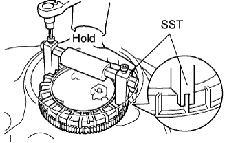
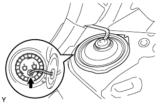
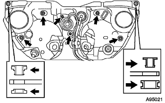
Using a 6 mm socket, set SST to the fuel pump gauge retainer.
- SST
- 09808-14020
- NOTICE:
- Do not use any other tools such as a screwdriver.
- HINT:
- Fit the tips of SST on the ribs of the retainer.
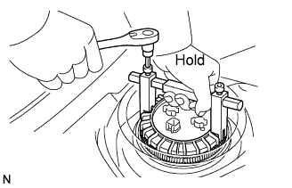
While holding the SST with by hand, remove the fuel pump gauge retainer.
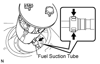
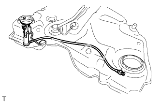
Disconnect the fuel suction tube.
Remove the fuel suction tube from the fuel tank.
- NOTICE:
- Make sure that the sender gauge arm does not bend.
- Do not damage the fuel sub-suction tube.
| 7. REMOVE REAR FLOOR SERVICE HOLE COVER |
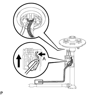
Remove the service hole cover and disconnect the fuel sender gauge connector.
| 8. REMOVE FUEL RETURN VENT TUBE SUB-ASSEMBLY |
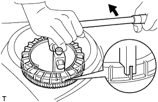
Using a 6 mm socket, set SST to the fuel pump gauge retainer.
Using a 6 mm socket, set SST to the fuel pump gauge retainer.
- SST
- 09808-14020
- NOTICE:
- Do not use any other tools such as a screwdriver.
- HINT:
- Fit the tips of SST on the ribs of the retainer.
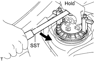
While holding the fuel suction tube with one hand, remove the fuel pump gauge retainer.
Remove the fuel return vent tube from the fuel tank.
- NOTICE:
- Be careful not to bend the arm of the sender gauge.
Remove the No. 1 fuel suction tube set gasket from the fuel tank.
Disconnect the fuel sender gauge connector.
Press down on the sender gauge claw labeled A. Then slide the sender gauge upward.
| 9. REMOVE EXHAUST PIPE ASSEMBLY |
Remove the exhaust pipe (Click here).
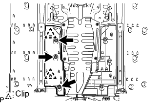
| 10. REMOVE FRONT FLOOR COVER CENTER RH |
Remove the 3 nuts, 2 clips and floor cover.
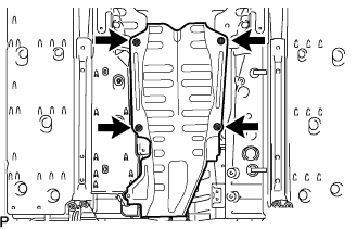
| 11. REMOVE FRONT FLOOR NO. 1 HEAT INSULATOR |
Remove the 4 nuts and heat insulator.
| 12. REMOVE PROPELLER WITH CENTER BEARING SHAFT ASSEMBLY |
Put matchmarks on both flanges.
Remove the 4 nuts, bolts and washers.
- HINT:
- If the flange connection is hard to separate, temporarily tighten one nut only and evenly tap the flange with a brass bar and hammer to separate the propeller shaft assembly from the differential companion flange.
Remove the 2 bolts, 2 center support bearing washers and center support bearing.
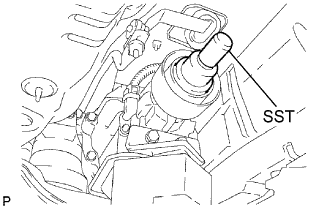
Insert SST in the transmission to prevent oil leakage.
- SST
- 09325-40010
- NOTICE:
- Be careful not to damage the oil seal.
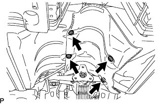
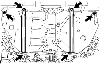
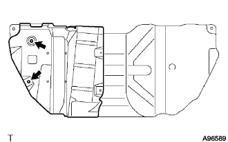
| 13. REMOVE NO. 2 FUEL TANK PROTECTOR |
Remove the 4 nuts and fuel tank protector.
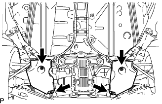
| 14. REMOVE NO. 1 DIFFERENTIAL SUPPORT PROTECTOR |
Remove the 4 nuts and differential support protector.
| 15. REMOVE NO. 2 DIFFERENTIAL SUPPORT PROTECTOR |
Remove the 4 nuts and differential support protector.
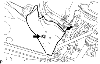
| 16. REMOVE REAR FLOOR SIDE MEMBER COVER LH |
Remove the 2 bolts and member cover.
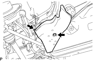
| 17. REMOVE REAR FLOOR SIDE MEMBER COVER RH |
Remove the 2 bolts and side member cover.
| 18. DISCONNECT PARKING BRAKE CABLE ASSEMBLY |
Remove the 2 parking brake cables from the 4 clamps.
Remove the 4 bolts and disconnect the 2 parking brake cables.
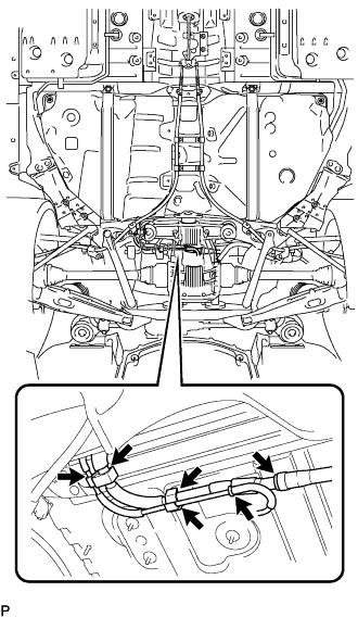
| 19. DISCONNECT FUEL TANK MAIN TUBE SUB-ASSEMBLY |
- NOTICE:
- Check for any dirt and foreign matter contamination in the pipe and around the connector. Clean them if necessary. Foreign matter may damage the O-ring or cause leaks in the seal between the pipe and connector.
- Do not use any tools to separate the pipe and connector.
- Do not forcefully bend or twist the nylon tube.
- Check for any dirt and foreign matter on the pipe seal surface. Clean it if necessary.
- Put the pipe and connector ends in plastic bags to prevent damage and dirt contamination.
- If the pipe and connector are stuck together, pinch the tube between your fingers and turn it carefully to free it. Then disconnect the tube.
Pinch and pull the main tube connector to disconnect the connector from the pipe.
| 20. DISCONNECT FUEL TANK TO FILLER PIPE HOSE |
Disconnect the filler pipe hose from the fuel tank filler pipe.
| 21. REMOVE FUEL EMISSION HOSE |
Remove the bracket.
Disconnect the 2 fuel emission hoses.
| 22. REMOVE FUEL TANK SUB-ASSEMBLY |
Remove the 2 nuts from the fuel tank.
Place a mission jack under the fuel tank.
Remove the 4 nuts and 2 fuel tank bands.
Install the 2 nuts.
| 23. REMOVE FUEL TANK MAIN TUBE SUB-ASSEMBLY |
Remove the 2 clamps and fuel tank main tube.
| 24. REMOVE FUEL TANK CUSHION |
Remove the tank cushions and fuel tank brackets.
| 25. REMOVE NO. 1 FUEL TANK PROTECTOR |
Remove the 2 nuts and fuel tank protector.